
Distributed power source system with storage battery

a technology of power source system and storage battery, which is applied in the direction of dc source parallel operation, active power filtering, transportation and packaging, etc., can solve the problems of system current change, power factor difference, and inability to perform swift and appropriate load control, etc., and achieve stable dc power

Active Publication Date: 2016-05-26
DIAMOND&ZEBRA ELECTRIC MFG CO LTD
View PDF2 Cites 16 Cited by
  • Summary
  • Abstract
  • Description
  • Claims
  • Application Information

AI Technical Summary

Benefits of technology

This present invention is a distributed power source system with a storage battery that can supply stable power to a load while quickly responding to changes in the load's power factor and performing reactive power compensation. This is achieved by controlling the power factor of the output current from the inverter to match that of the load current. The system also includes a target amplitude for the active current of the inverter output current and a control section to ensure that the active current amplitude coincides with the load current's amplitude. Furthermore, when there is excess power, the system controls the bidirectional converter to charge the battery with the excess power, ensuring effective use of the battery.

Problems solved by technology

However, in these cases, it may be impossible to perform swift and appropriate control for the load that needs to be controlled as described above, merely by detecting a power factor of system current as in conventional case.
However, immediately after power of the load has changed, inverter output current has not changed yet, and therefore reactive current is supplied from the power system, whereby change in the power factor of system current occurs.
Thus, a difference occurs between the power factor of system current and a power factor of load current, and appropriate response to change in the power factor of load current cannot be attained.
As a result, supply of power may become unstable.

Method used


Image

  • Distributed power source system with storage battery
  • Distributed power source system with storage battery
  • Distributed power source system with storage battery

Examples


Embodiment Construction

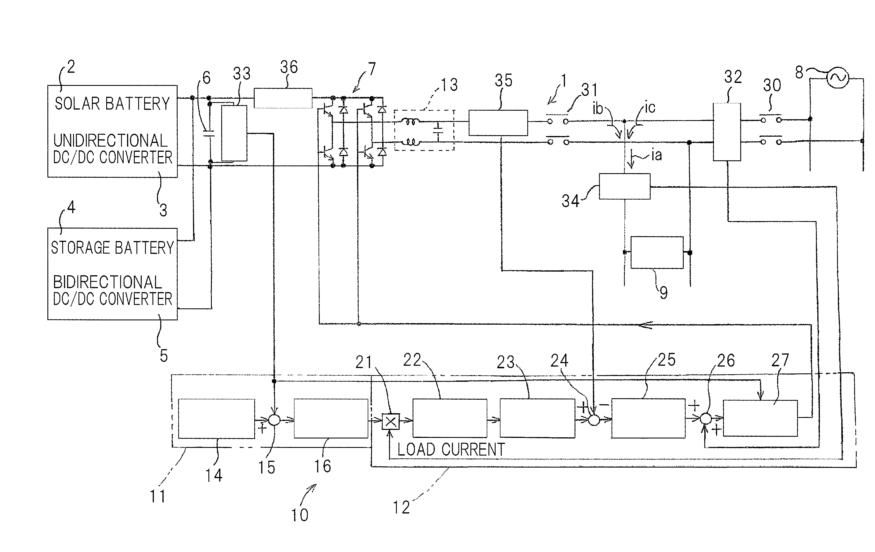
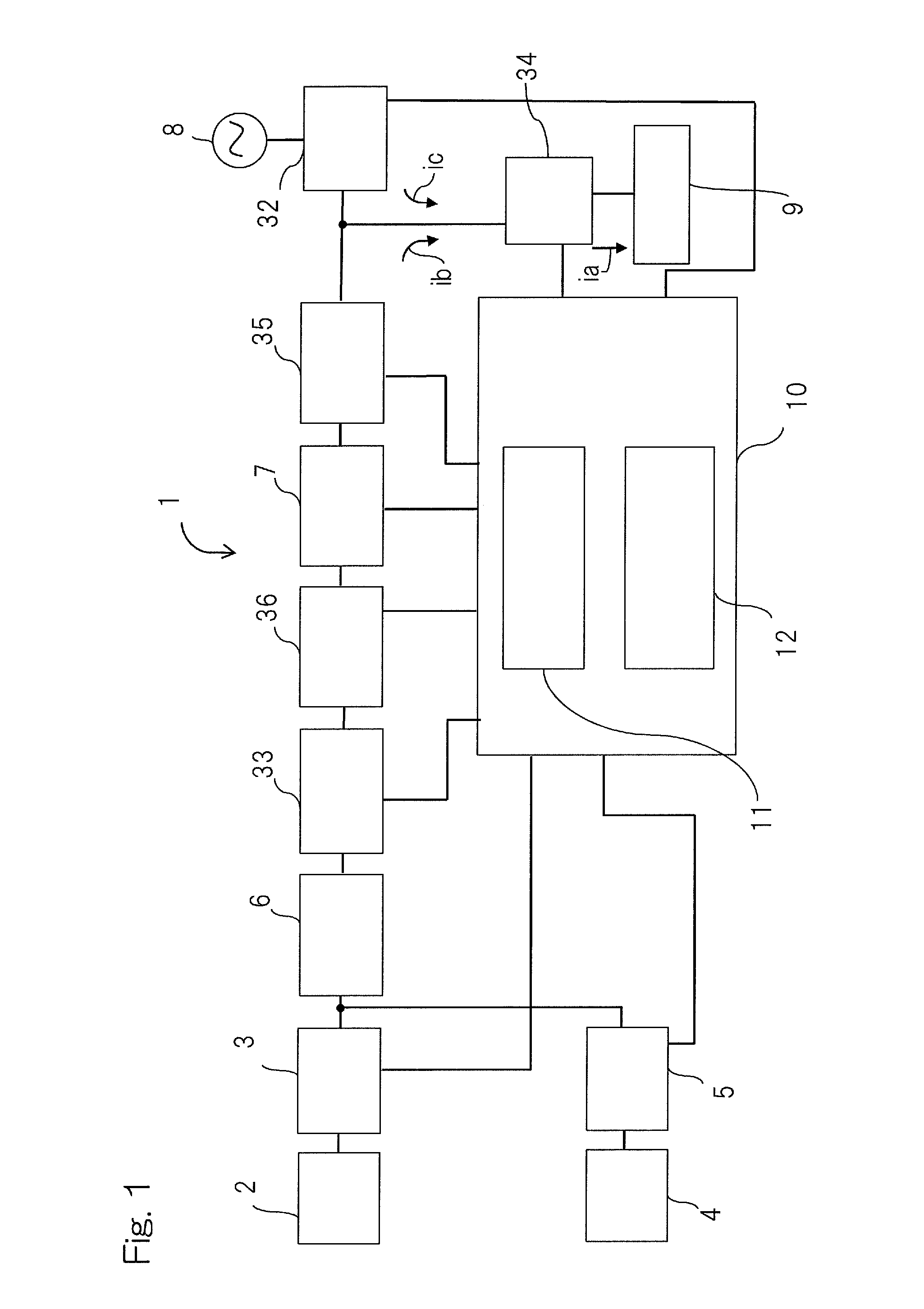
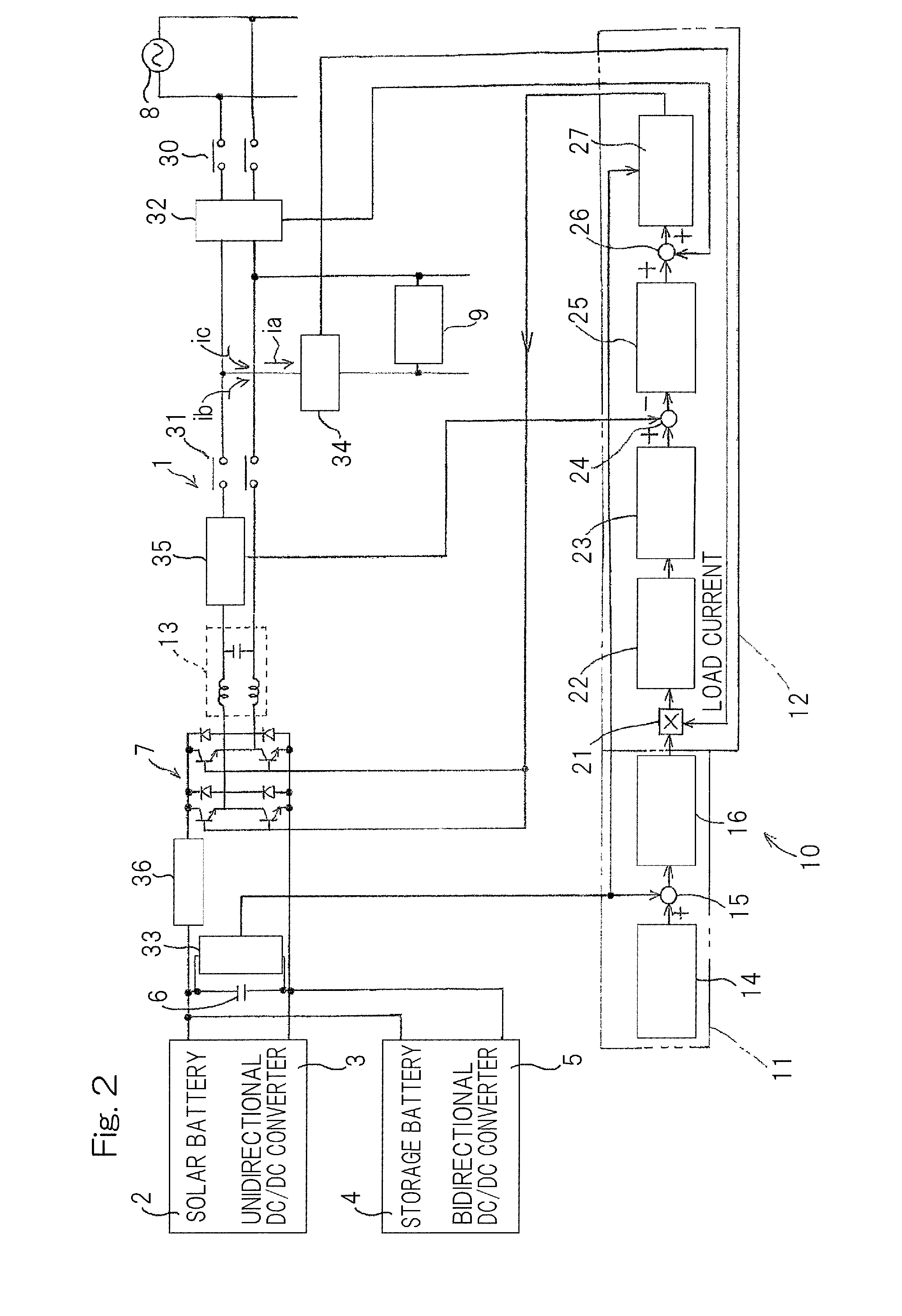
[0024]Hereinafter, embodiments of the present invention will be described with reference to the drawings. FIG. 1 is a block diagram showing a distributed power source system 1 with a storage battery according to the first embodiment of the present invention. The distributed power source system 1 with a storage battery is to effectively utilize power of a distributed power source such as a solar battery while effectively using a storage battery, and is used for, for example, when a peak of power consumption is about to exceed an upper limit value, performing compensation by power stored in a storage battery, to perform peak cut.

[0025]The distributed power source system 1 in FIG. 1 includes: a distributed power source such as a solar battery 2; a unidirectional converter (DC / DC converter) 3 which performs DC conversion of DC power of the solar battery 2; a storage battery 4 which performs charging and discharging; a bidirectional converter (DC / DC converter) 5 which performs bidirectio...


PUM


Abstract

The present system 1 includes a distributed power source 2, a storage battery 4, a bidirectional inverter 7 having a smoothing capacitor 6 on its DC side, and a control section 10 for controlling the entire system, and supplies AC power to a load 9 while being interconnected with a power system 8. When active power supplied from the distributed power source 2 and / or the storage battery 4 to the smoothing capacitor 6 is equal to or greater than active power of load power, the control section 10 controls a power factor of inverter output current outputted from the bidirectional inverter 7 so as to coincide with a power factor of load current flowing to the load 9.

Description

CROSS REFERENCE TO THE RELATED APPLICATION[0001]This application is based on and claims Convention priority to Japanese patent application No. 2014-236373, filed Nov. 21, 2014, the entire disclosure of which is herein incorporated by reference as a part of this application.BACKGROUND OF THE INVENTION[0002]1. Field of the Invention[0003]The present invention relates to a distributed power source system with a storage battery, which charges the storage battery with DC power of a distributed power source such as a solar battery, and supplies AC power to a load while being interconnected with a commercial power system or power grid.[0004]2. Description of Related Art[0005]Conventionally, there is known a distributed power source system with a storage battery, which effectively utilizes power of a distributed power source such as a solar power while effectively using the storage battery. In this system, an inverter is provided for performing system interconnection for DC power of the sol...

Claims


Application Information

Patent Timeline
IPC IPC(8): H02J3/18H02J7/35
CPCH02J7/35H02J3/18H02J3/1842H02J3/32Y02E40/20
Inventor SUGIMOTO, HIDEHIKO
Owner DIAMOND&ZEBRA ELECTRIC MFG CO LTD
Learn More