Heat dissipation device

Active Publication Date: 2016-05-26
ASIA VITAL COMPONENTS SHENZHEN CO LTD
View PDF5 Cites 1 Cited by
  • Summary
  • Abstract
  • Description
  • Claims
  • Application Information

AI Technical Summary

Benefits of technology

[0007]Another object of the present invention is to provide a heat dissipation device that has a heat transfer member being prevented from deformation.
[0008]To achieve the above and other objects, the present invention provides a heat dissipation device including a heat dissipation member, a heat transfer member, and a reinforcing member. The heat transfer member has one side attached to the heat dissipation member, and two opposite lateral edges thereof are respectively provided with at least one connection portion. The r

Problems solved by technology

Therefore, it is the foremost issue in the contemporary electronic industry to develop high-efficiency heat dissipation devices.
With the advancement of the technology and the demand for thin and light products, the heat transfer member is n

Method used


Image

  • Heat dissipation device
  • Heat dissipation device
  • Heat dissipation device

Examples


Example

[0017]The present invention will now be described with some preferred embodiments thereof and by referring to the accompanying drawings. For the purpose of easy to understand, elements that are the same in the preferred embodiments are denoted by the same reference numerals.

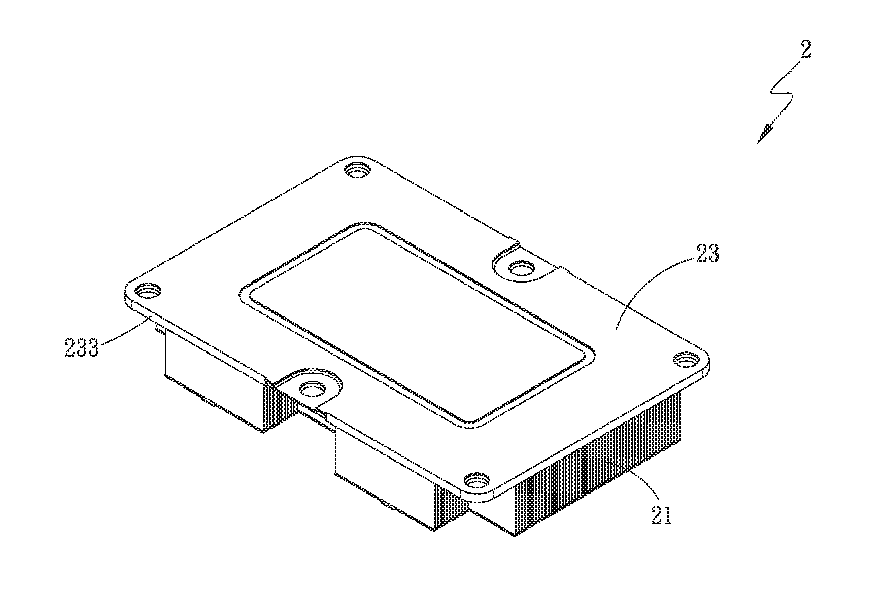
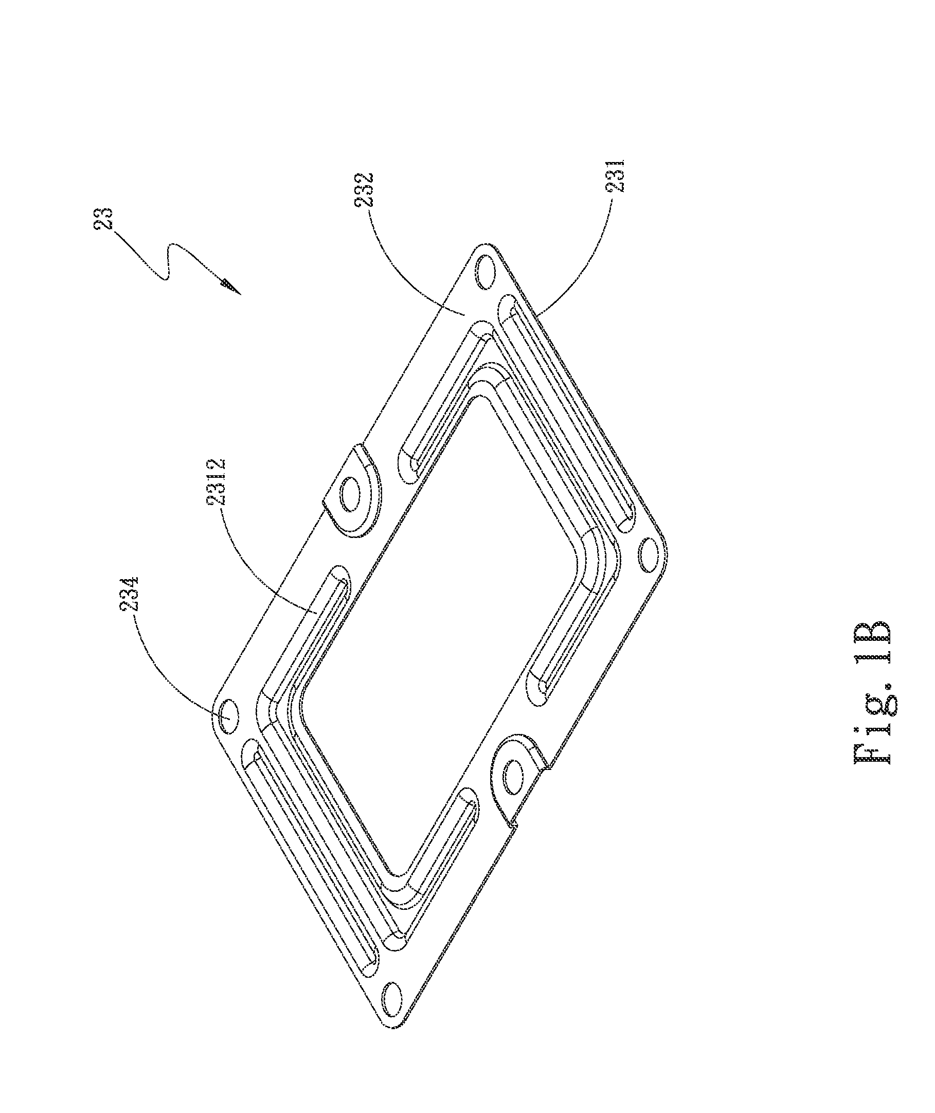
[0018]Please refer to FIGS. 1A and 1B, which are top and bottom perspective views, respectively, of a reinforcing member 23 included in a heat dissipation device 2 according to a first embodiment of the present invention, and to FIGS. 2A and 2B, which are exploded and assembled perspective views, respectively, of the heat dissipation device 2 according to the first embodiment of the present invention. As shown, the heat dissipation device 2 includes a heat dissipation member 21, a heat transfer member 22, and a reinforcing member 23. The heat dissipation member 21 includes a plurality of heat radiation fins 211 and defines at least one recessed portion 212.

[0019]The heat transfer member 22 has one side attached t...


PUM


Abstract

A heat dissipation device includes a heat dissipation member, a heat transfer member, and a reinforcing member. The heat transfer member has one side attached to the heat dissipation member, and two opposite lateral edges thereof are respectively provided with at least one connection portion and at least one through hole. The reinforcing member is connected to the other side of the heat transfer member, and two opposite lateral edges thereof are respectively formed with at least one mating connection portion for correspondingly connecting to the connection portion. The reinforcing member is provided at a central portion with an opening. With these arrangements, the heat transfer member can bear a larger locking force when the heat dissipation member is locked thereto, and is also prevented from deformation.

Description

FIELD OF THE INVENTION[0001]The present invention relates to a heat dissipation device, and more specifically, to a heat dissipation device that has a heat transfer member not only capable of bearing a larger locking force when a heat dissipation member is locked thereto, but also prevented from deformation.BACKGROUND OF THE INVENTION[0002]As the advancement of technology, the electronic elements have higher and higher operation performance, so that the demand for high efficiency heat dissipation unit has also increased. In order to increase heat dissipation effect, the conventional heat dissipation units usually adopt a stacked heat radiation fin assembly, and continuous developments have also been made in heat dissipation fins. Therefore, it is the foremost issue in the contemporary electronic industry to develop high-efficiency heat dissipation devices. Alternatively, on the electronic elements, heat dissipation members are disposed to cool the electronic elements. The heat dissi...

Claims


Application Information

Patent Timeline
IPC IPC(8): H05K7/20F28F13/00
CPCF28F13/00H05K7/2039H01L23/367H01L23/3672H01L23/4006H01L23/427H01L23/467H01L2924/0002H01L2924/00
Inventor LIN, YUAN-YI
Owner ASIA VITAL COMPONENTS SHENZHEN CO LTD
Why Eureka
Try Eureka