Eureka AIR delivers breakthrough ideas for toughest innovation challenges, trusted by R&D personnel around the world.

Fluid container displacement pump

Inactive Publication Date: 2016-06-02
BAYER HEALTHCARE LLC
View PDF0 Cites 0 Cited by
  • Summary
  • Abstract
  • Description
  • Claims
  • Application Information

AI Technical Summary

Benefits of technology

[0008]The cover member may include a plate disposed in the pump chamber and a shaft connected to the plate, with the shaft extending through a second opening in the pump housing. An outer surface of the shaft of the cover member may be adapted to be in operational engagement with a ratcheting member positioned externally on the pump housing. Outlet tubing may be in fluid communication with the pump chamber to deliver the pre-determined volume of fluid dispensed from the pump chamber to a patient. An outlet control valve may be provided in the outlet tubing. The outlet control valve may be configured to dispense the pre-determined volume of fluid from the pump chamber. A bladder may be disposed in the pump chamber to hold the fluid. A plate member may be connected to a distal end of the actuating member and positioned in the pump chamber. The plate member may extend across a diameter of the pump chamber. A lower surface of the cover member may define a recess shaped to receive a distal end of the at least one actuating member therein. An added weight may be provided on the cover member. An actuating device may operationally control the at least one actuating member. A second actuating device may also operationally control the cover member.
[0009]In another embodiment, a fluid container displacement pump is provided. The fluid container displacement pump includes a pump housing defining a pump chamber for holding a fluid to be dispensed to a patient, at least one actuating member movable relative to the pump housing and extending through at least one first opening defined in the pump housing, a fluid reservoir defining a reservoir chamber in fluid communication with the pump housing, and a control valve controlling fluid flow between the reservoir chamber and the pump chamber. Discrete movement of one or more of the at least one actuating member into the pump chamber causes a pre-determined volume of fluid in the pump chamber corresponding to the discrete movement to be dispensed from the pump chamber. Movement of the at least one actuating member in an opposing direction retracts the at least one actuating member from the pump chamber. Upon the pre-determined volume of fluid being dispensed from the pump chamber, fluid from the reservoir chamber enters the pump chamber under the flow control provided by the control valve.
[0010]An outlet control valve may be connected to the pump chamber to control fluid flow to outlet tubing conducting the pre-determined volume of fluid to the patient. The control valve and the outlet control valve may each comprise one-way check valves. Outlet tubing may be in fluid communication with the pump chamber to deliver the pre-determined volume of fluid dispensed from the pump chamber to a patient. A bladder may be disposed in the fluid reservoir to hold the fluid. An actuating device may operationally control the at least one actuating member. Upon a fluid pressure in the pump chamber becoming less than a fluid pressure in the reservoir chamber, fluid from the reservoir chamber may be automatically suppl

Problems solved by technology

One limitation of the syringe-based fluid injection system is the need to fill, refill and/or replace the disposable syringes prior to each patient procedure.
However, there are several disadvantages present in the foregoing positive displacement pump platforms kn

Method used


Image

  • Fluid container displacement pump
  • Fluid container displacement pump
  • Fluid container displacement pump

Examples


Example

[0027]For purposes of the description hereinafter, spatial orientation terms, if used, shall relate to the referenced embodiment as it is oriented in the accompanying drawing, figures, or otherwise described in the following detailed description. However, it is to be understood that the embodiments described hereinafter may assume many alternative variations and embodiments. It is also to be understood that the specific devices illustrated in the accompanying drawings, figures, and described herein are simply exemplary and should not be considered as limiting.

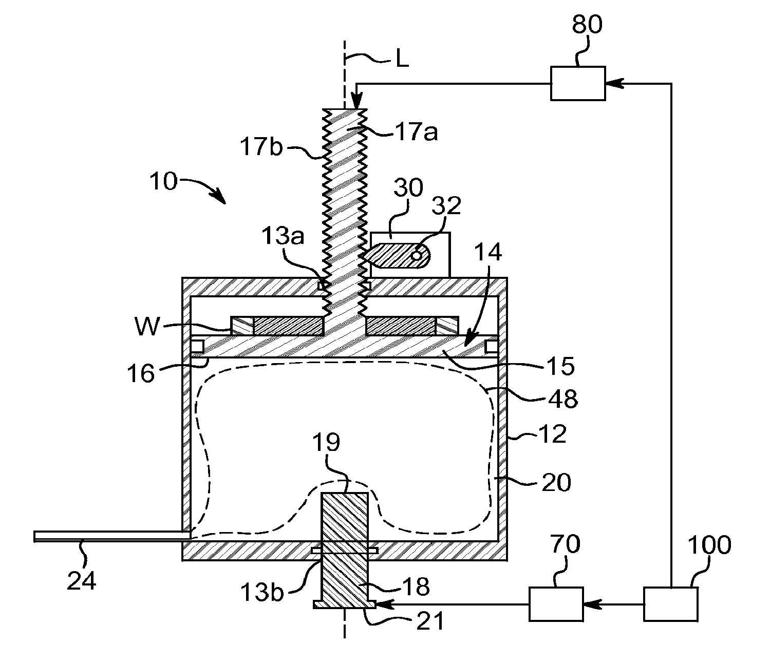
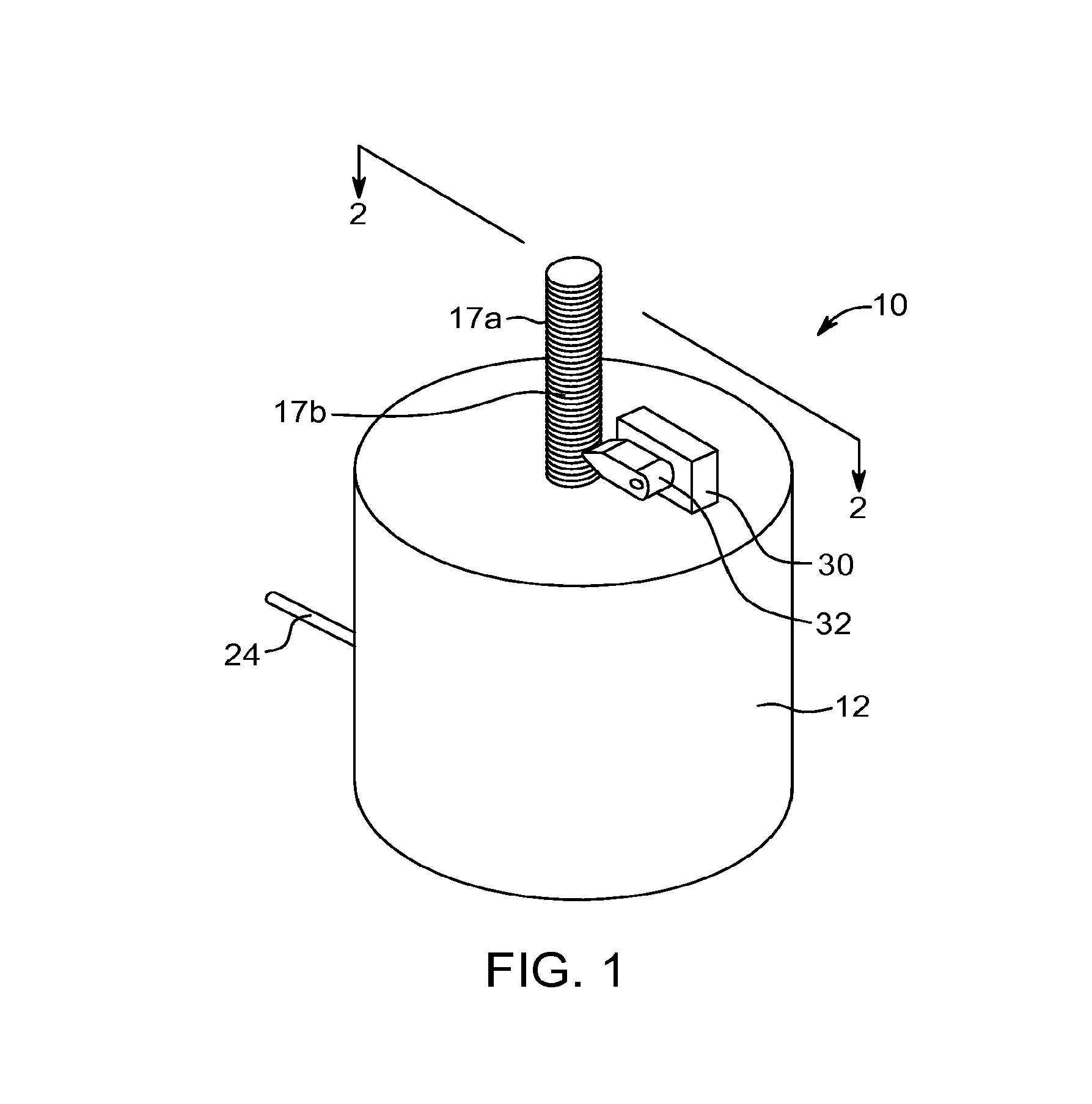
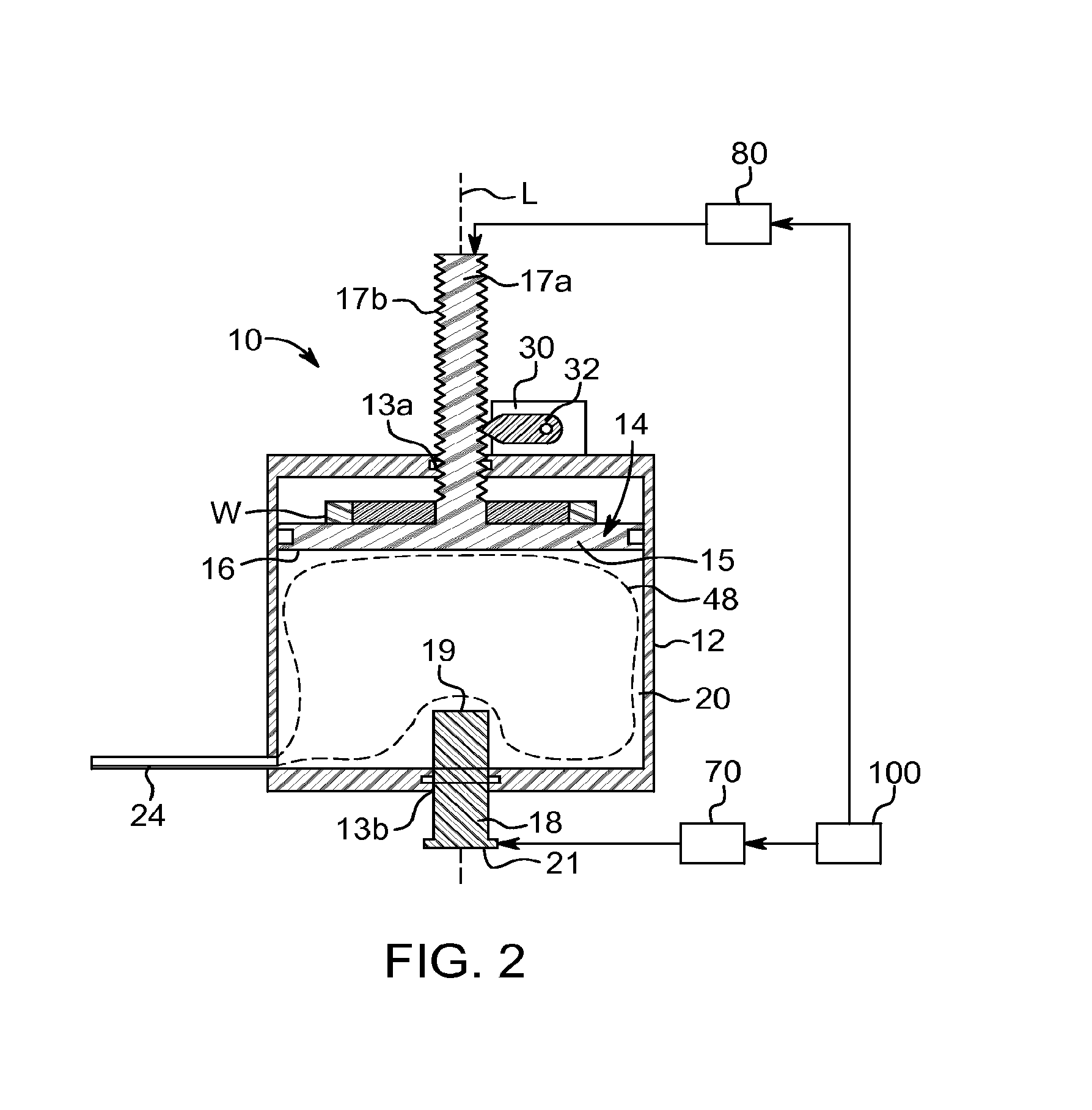
[0028]Referring to the drawings in which like reference characters refer to like parts throughout the several views thereof, a fluid container displacement pump 10 (hereinafter “pump 10”) and method for fluid delivery using the pump 10 will be described herein. Referring to FIGS. 1 and 2, the pump 10 is used as part of a fluid delivery system to deliver fluid to a patient. In this embodiment, the pump 10 generally includes a pu...


PUM


Abstract

A fluid container displacement pump, in one embodiment, includes a pump housing defining a pump chamber for holding a fluid to be dispensed to a patient, at least one actuating member movable relative to the pump housing and extending through at least one opening defined in the pump housing, and a cover member disposed in the pump chamber opposite the actuating member. The fluid container displacement pump, in another embodiment, includes a pump housing defining a pump chamber for holding a fluid to be dispensed to a patient, at least one actuating member movable relative to the pump housing and extending through at least one opening defined in the pump housing, a fluid reservoir defining a reservoir chamber in fluid communication with the pump housing, and a control valve controlling fluid flow between the reservoir chamber and the pump chamber.

Description

CROSS-REFERENCE TO RELATED APPLICATIONS[0001]This application claims the benefit of U.S. Provisional Application No. 61 / 845,130, filed Jul. 11, 2013, the disclosure of which is hereby incorporated in its entirety by reference.BACKGROUND OF THE INVENTION[0002]1. Field of the Invention[0003]The present disclosure is directed to a fluid delivery system having a fluid pumping device for discrete volume fluid delivery applications in medical diagnostic and therapeutic procedures.[0004]2. Description of Related Art[0005]There are a number of medical procedures which require the delivery of fluids to a patient in a precisely controlled or discrete manner. To facilitate this requirement, a variety of fluid delivery systems have been designed and implemented. A common fluid delivery system that is used to deliver a fluid to a patient is a gravity-feed system. In this system, a bag holding the fluid is supported above the level of the patient's body and the flow rate of the fluid to the patie...

Claims


Application Information

Patent Timeline
IPC IPC(8): A61M5/145
CPCA61M5/1452A61M2205/10A61M2005/14533A61M5/14216A61M5/148A61M5/16854G05D7/0676B67B7/24
Inventor COWAN, KEVIN P.TUCKER, BARRY L.RHINEHART, EDWARD J.
Owner BAYER HEALTHCARE LLC
Why Eureka
Eureka Blog
Learn More