Power recovery system

a power recovery system and power technology, applied in the direction of multi-stage water/sewage treatment, piston pumps, separation processes, etc., can solve the problems of small adverse effect on the energy efficiency of the entire power recovery system, difficult to increase the performance of pumps and turbine devices, etc., and achieve the effect of reducing the total energy consumption

Active Publication Date: 2009-04-30
EBARA CORP
View PDF11 Cites 41 Cited by
  • Summary
  • Abstract
  • Description
  • Claims
  • Application Information

AI Technical Summary

Benefits of technology

[0023]The present invention has been made in view of the above problems in the art. It is therefore an object of the present invention to provide a power recovery system which is capable of reducing the total energy consumption in a process such as an industrial treating process or a fluid refining process including the delivery of a fluid under a high pressure.

Problems solved by technology

Furthermore, the power recovery pump turbine may be a low-head device for producing a relatively low pressure loss caused by the control valve or the like, and has a very small adverse effect on the energy efficiency of the entire power recovery system even through the power recovery pump turbine is of low performance.
Pumps and turbine devices are difficult to be increased in performance if their heads are large compared with the flow rates.

Method used


Image

  • Power recovery system
  • Power recovery system
  • Power recovery system

Examples


first embodiment

Power Recovery System

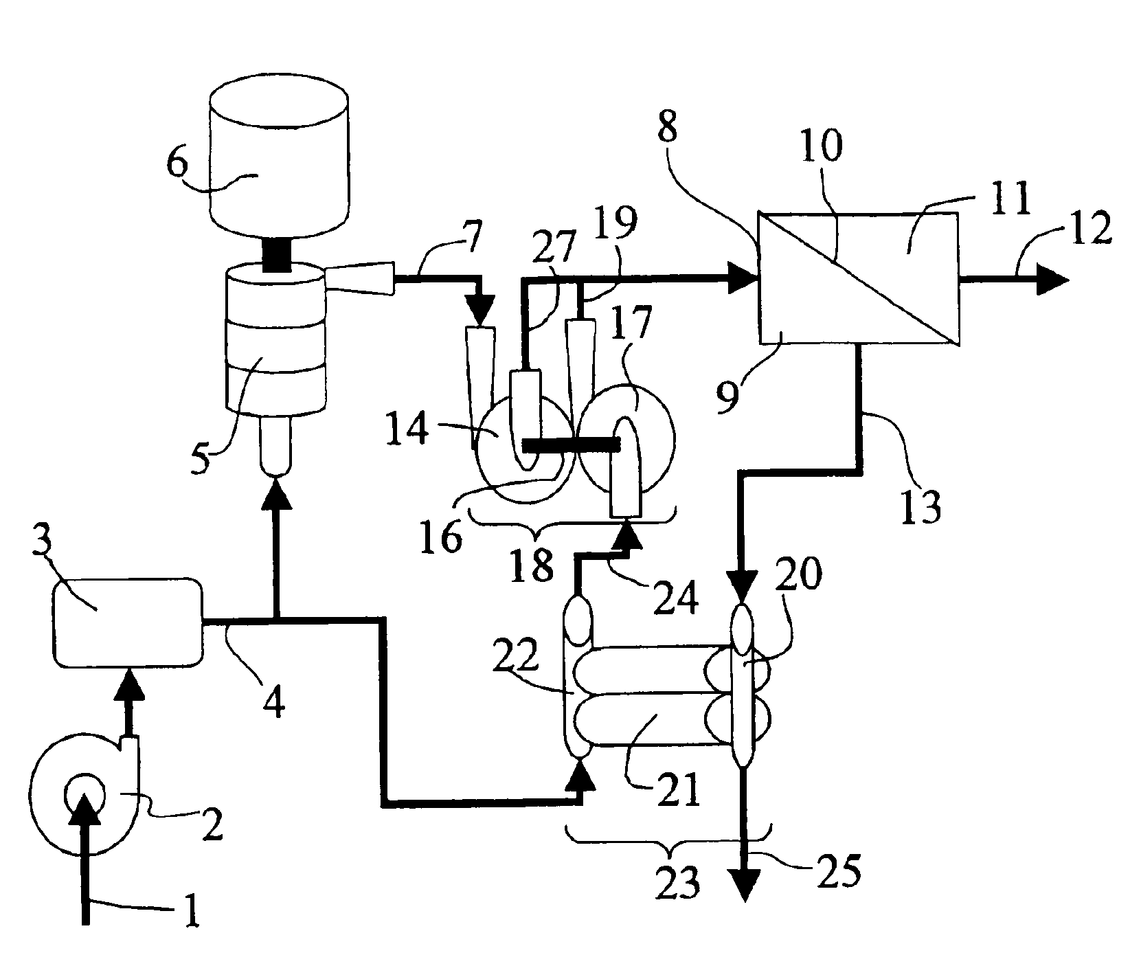
[0115]FIG. 3 is a schematic diagram of a power recovery system according to a first embodiment of the present invention. As shown in FIG. 3, when seawater 1 is pumped into a seawater desalination plant by an intake pump 2, the seawater 1 is processed to have certain water qualities by a pretreatment system 3, and then pressurized and delivered into a high-pressure line 7 by a high-pressure pump 5 that is driven by an electric motor 6. The high-pressure pump 5 may be controlled by a control valve or an inverter for flow rate control. Part of the seawater in a high-pressure chamber 9 of the reverse osmosis membrane cartridge 8 passes through a reverse osmosis membrane 10 against the reverse osmosis pressure and is desalinated, and then desalinated water 12 is taken out from the reverse osmosis membrane cartridge 8. The remaining concentrated seawater with a high salt content is discharged under pressure as a reject from the reverse osmosis membrane cartridge 8 int...

second embodiment

Power Recovery System

[0118]FIG. 4 is a schematic diagram of a power recovery system according to a second embodiment of the present invention. The power recovery system shown in FIG. 4 includes a positive-displacement piston pump and a power recovery pump turbine that are combined in a hybrid system, the power recovery pump turbine having a turbine impeller actuatable by part of the concentrated seawater from the reverse osmosis membrane cartridge 8.

[0119]As shown in FIG. 4, when seawater 1 is pumped into a seawater desalination plant by an intake pump 2, the seawater 1 is processed to have certain water qualities by a pretreatment system 3, and then pressurized and delivered via a high-pressure line 7 into a reverse osmosis membrane cartridge 8 by a high-pressure pump 5 that is driven by an electric motor 6. The high-pressure pump 5 may be controlled by a control valve or an inverter for flow rate control. Part of the seawater in a high-pressure chamber 9 of the reverse osmosis mem...


PUM

PropertyMeasurementUnit
pressureaaaaaaaaaa
pressureaaaaaaaaaa
poweraaaaaaaaaa

Abstract

A power recovery system is used for reducing the total energy consumption in a process such as an industrial treating process or a fluid refining process including the delivery of a fluid under a high pressure. The power recovery system includes a high-pressure pump for pressuring raw water, a reverse osmosis membrane cartridge for treating high-pressure water discharged from the high-pressure pump with a reverse osmosis membrane to produce treated water, a positive-displacement piston pump for pressuring raw water under the pressure of concentrated water which is discharged from the reverse osmosis membrane cartridge without being treated by the reverse osmosis membrane, and a power recovery pump turbine for boosting the pressurized raw water discharged from the positive-displacement piston pump and adding the boosted water to the high-pressure water discharged from the high-pressure pump. The power recovery pump turbine is actuated by pressurized water generated in the power recovery system.

Description

BACKGROUND OF THE INVENTION[0001]1. Field of the Invention[0002]The present invention relates to a power recovery system for reducing the total energy consumption in a process such as an industrial treating process or a fluid refining process including the delivery of a fluid under a high pressure. Particularly, the present invention is preferably used for a power recovery system serving as a consumption energy reducing means in a seawater desalination plant which employs a reverse osmosis membrane method for removing salinity from seawater.[0003]2. Description of the Related Art[0004]Industrial treating processes or fluid refining processes that use a high-pressure fluid require high cost of power to refine the high-pressure fluid. Several methods have been attempted to recover energy from the high-pressure fluid after the processes. As a typical example of such processes according to the related art, a seawater desalination plant which employs a reverse osmosis membrane method and...

Claims


Application Information

Patent Timeline
Patent Type & Authority Applications(United States)
IPC IPC(8): F04B43/00C02F1/44F04B35/00
CPCB01D61/06C02F2209/42C02F2103/08C02F1/441Y02A20/131Y02W10/30
Inventor TAKITA, SHIGEOSHINODA, MASAOYAMANAKA, TAKASHIGOTO, AKIRAKANNO, HIDEKI
Owner EBARA CORP
Why Eureka
Try Eureka