Hydraulic braking system and method

a braking system and hydraulic technology, applied in the direction of brake action initiation, brake system, vehicle components, etc., can solve the problems of driver not being able to call on the assistance system, driver cannot monitor the movement and surroundings of the vehicle, and assistance force cannot be made available on the part of the assistance system, so as to simplify the control of the braking system

Active Publication Date: 2016-06-02
ROBERT BOSCH GMBH
View PDF9 Cites 19 Cited by
  • Summary
  • Abstract
  • Description
  • Claims
  • Application Information

AI Technical Summary

Benefits of technology

[0024]In an embodiment, the secondary calculating device is coupled to the first interrupting arrangement and is embodied to apply control to the first interrupting arrangement. When control is applied both to the secondary pressure generator and to the first interrupting arrangement by the secondary calculating device, this simplifies control of the braking system in the event of a fault in the primary pressure generator.
[0025]In an embodiment, the primary calculating device and the second calculating device are disposed in different control units. This increases the availability of the primary calculating device and of the secondary calculating device, since a fault in one individual control unit does not result in a failure of both calculating devices.
[0026]In an embodiment, the primary calculating device and the secondary calculating device each have a separate energy supply system. This further increases the availability of the primary calculating device and of the secondary calculating device, since an individual fault in one energy supply system does not result in a failure of both calculating devices.
[0027]In an embodiment, the secondary brake pressure generator has a single-circuit pump, in particular a single-piston pump. This makes it possible to furnish an uncomplicated secondary brake pressure generator to which control can be applied in simple fashion.

Problems solved by technology

The driver therefore cannot monitor the movement and surroundings of the vehicle.
The result is that in some circumstances the driver cannot be called upon in the event of a required braking operation.
In the event of failure of the pressure control cylinder, an assistance force can no longer be made available on the part of an assistance system.
Such a failure can be, for example, a failure of the engine, with the result that a pressure increase by way of an assistance force is no longer possible, but instead can be provided only by the driver using muscle power.

Method used


Image

  • Hydraulic braking system and method
  • Hydraulic braking system and method
  • Hydraulic braking system and method

Examples


Embodiment Construction

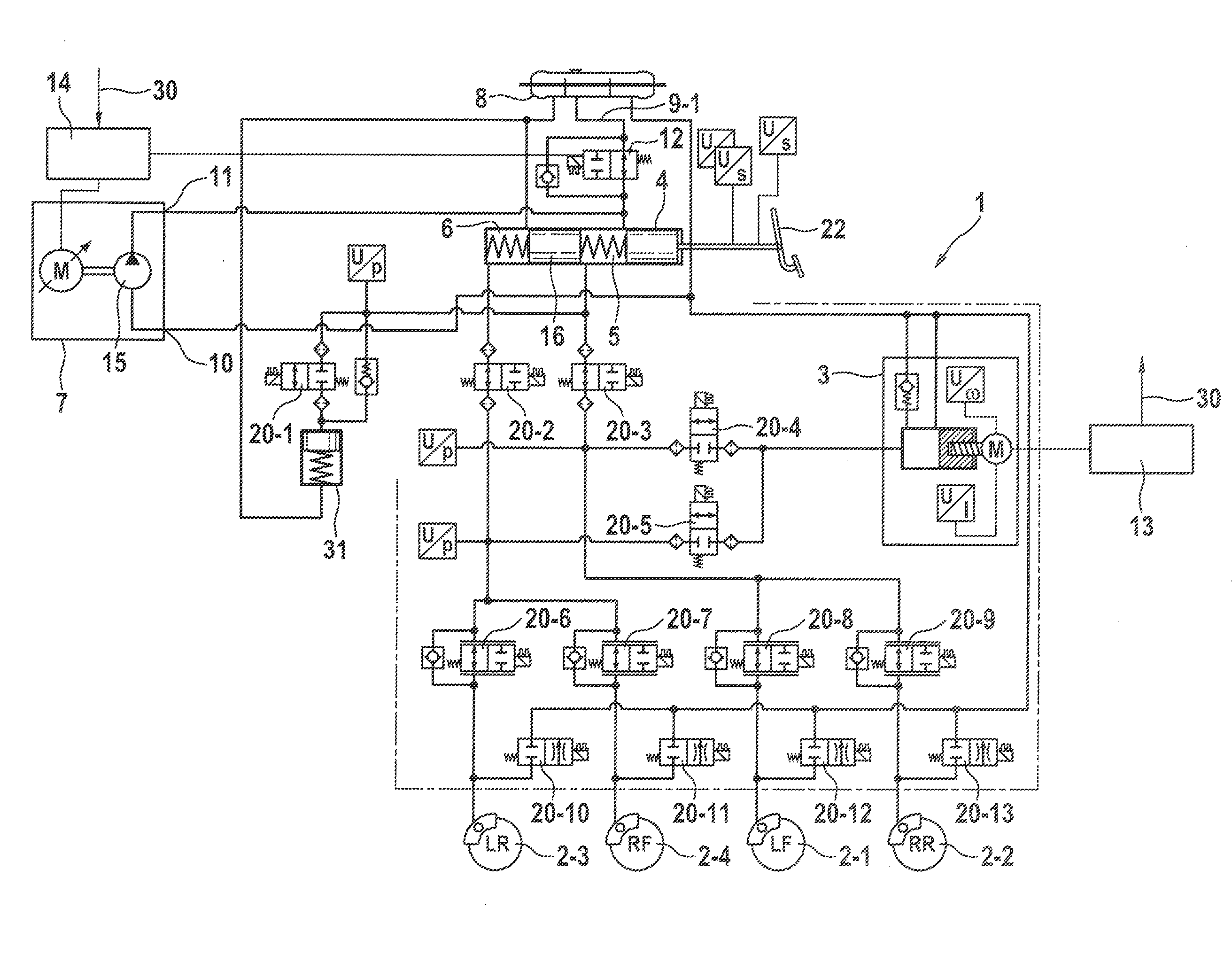
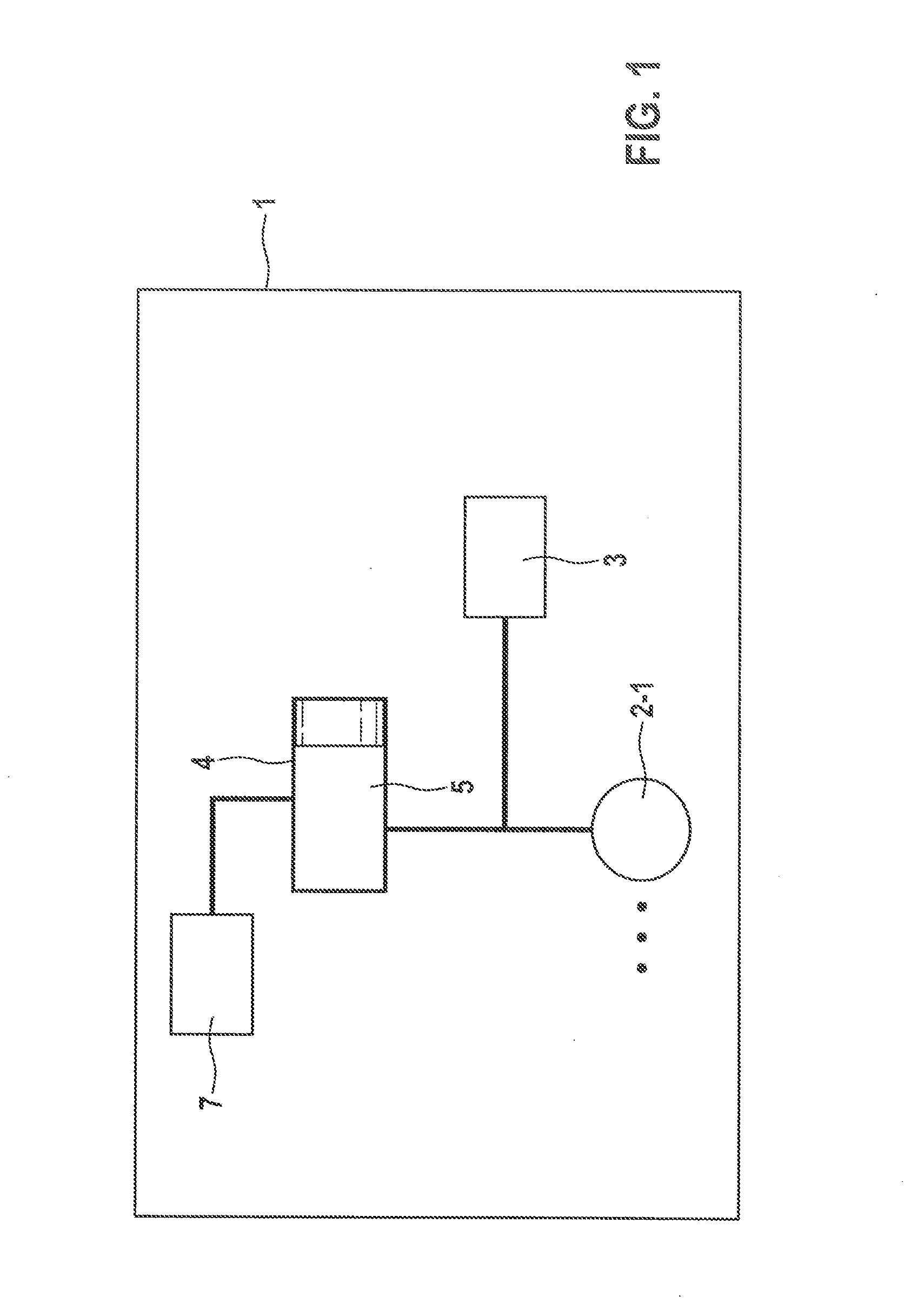
[0038]FIG. 1 is a block diagram of an embodiment of hydraulic braking system 1 according to the present invention.

[0039]Hydraulic braking system 1 has a wheel brake cylinder 2-1 that is hydraulically coupled to a primary brake pressure generator 3 and to a brake master cylinder 4. Further wheel brake cylinders are indicated by three dots.

[0040]Wheel brake cylinder 2-1 can be impinged upon by pressure, by way of a hydraulic fluid, via both primary pressure generator 3 and brake master cylinder 4.

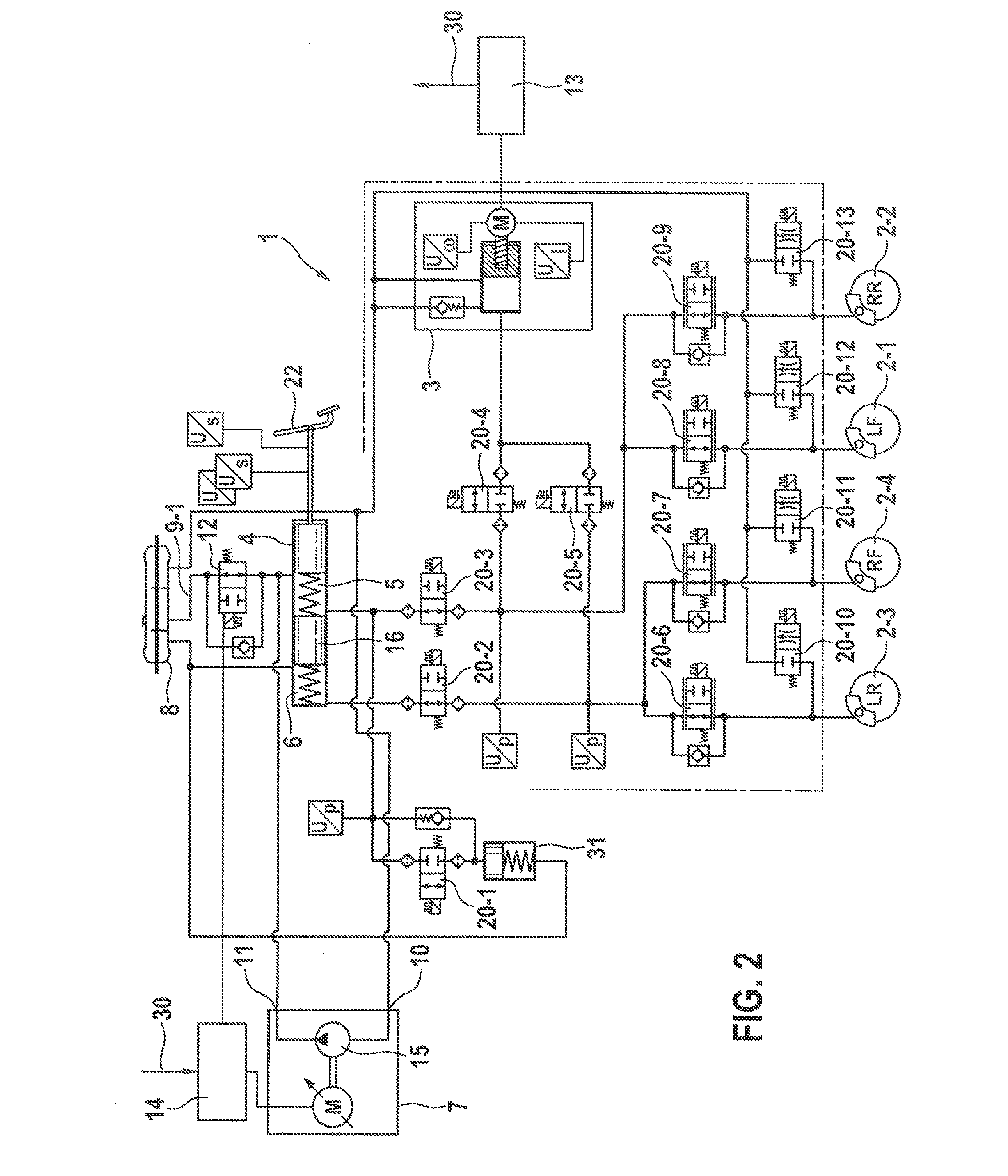
[0041]Wheel brake cylinder 2-1 is coupled for that purpose to a first pressure chamber 5 of brake master cylinder 4. In further embodiments, brake master cylinder 4 can additionally have a second pressure chamber 6 that can be hydraulically coupled, for example, to further wheel brake cylinders. An embodiment of this kind is shown, for example, in FIGS. 2 to 4.

[0042]Lastly, hydraulic braking system 1 has a secondary brake pressure generator 7 that is hydraulically coupled to first pressure ch...


PUM


Abstract

A hydraulic braking system having: at least one wheel brake cylinder; a primary brake pressure generator that is disconnectably hydraulically coupled to the at least one wheel brake cylinder and is embodied to impinge upon the at least one wheel brake cylinder with pressure by way of a hydraulic fluid; a brake master cylinder that has at least one first pressure chamber and to which at least one wheel brake cylinder is hydraulically coupled; and a secondary brake pressure generator that is coupled to the first pressure chamber of the brake master cylinder and is embodied to impinge upon the first pressure chamber of the brake master cylinder with pressure, the secondary brake pressure generator being controllable independently of the primary brake pressure generator. Also disclosed is a related method.

Description

RELATED APPLICATION INFORMATION[0001]The present application claims priority to and the benefit of German patent application No. 10 2014 224 467.6, which was filed in Germany on Nov. 28, 2014, the disclosure of which is incorporated herein by reference.FIELD OF THE INVENTION[0002]The present invention relates to a hydraulic braking system and to a method for operating a hydraulic braking system.BACKGROUND INFORMATION[0003]In modern vehicles, a plurality of driver assistance systems assist the driver with driving the vehicle. Systems that take over acceleration and braking, as well as steering of the vehicle, from the driver in various situations are increasingly being used in passenger cars. When control of the vehicle is entirely taken over from the driver, the term “highly automated driving” or “autonomous driving” is also used.[0004]In highly automated driving, the driver can engage in activities other than controlling the vehicle while traveling. The driver therefore cannot moni...

Claims


Application Information

Patent Timeline
Patent Type & Authority Applications(United States)
IPC IPC(8): B60T13/14B60T13/74
CPCB60T13/745B60T13/142B60T8/40B60T13/686B60T7/042B60T8/4081B60T13/146B60T13/662
Inventor BAUER, URSKUNZ, MICHAELKUHLMAN, RYAN
Owner ROBERT BOSCH GMBH
Why Eureka
Try Eureka