Air intake heater system and methods

Inactive Publication Date: 2016-06-02
HIDRIA AET
View PDF20 Cites 3 Cited by
  • Summary
  • Abstract
  • Description
  • Claims
  • Application Information

AI Technical Summary

Benefits of technology

The patent describes a method for starting an air heater system in an engine. This method helps to quickly heat up the engine and reduces the amount of heat that needs to be accumulated while the engine is starting. By controlling the supply of power to the heating element of the air heater, the method allows for a more efficient use of electricity and a quicker engine start. The method also includes steps for activating the starter motor and heating the air heater again if the engine is still not ready to start. This method can make the engine start up faster and with less heat accumulation.

Problems solved by technology

As internal combustion engine systems become more and more complex, the pathway through which the intake air flows to the cylinders of the internal combustion engine system becomes more complex.
Due to the complex air flows and constraints within engine compartments, the location of air heaters may not be optimal such that straight through flow of air may be undesirable.
The controller of the air intake heater system will thus control large currents and can generate a large amount of heat.
First, preheating the air intake heater system, in some instances, can take as long as 20 seconds.
Second, the larger amount of material needed for the heating element to accumulate heat for engine start increases the cost of the air intake heater system.
The third problem is associated with long preheating times. When a long preheating time is used, a significant part of energy (estimated to be greater than 30%) in some instances is lost to heat transfer from the heating ribbon to adjacent components of the engine such as to the air intake housing or intake manifold, and then, from there, to the air within the engine compartment surrounding the engine and the air intake system.

Method used


Image

  • Air intake heater system and methods
  • Air intake heater system and methods
  • Air intake heater system and methods

Examples


Embodiment Construction

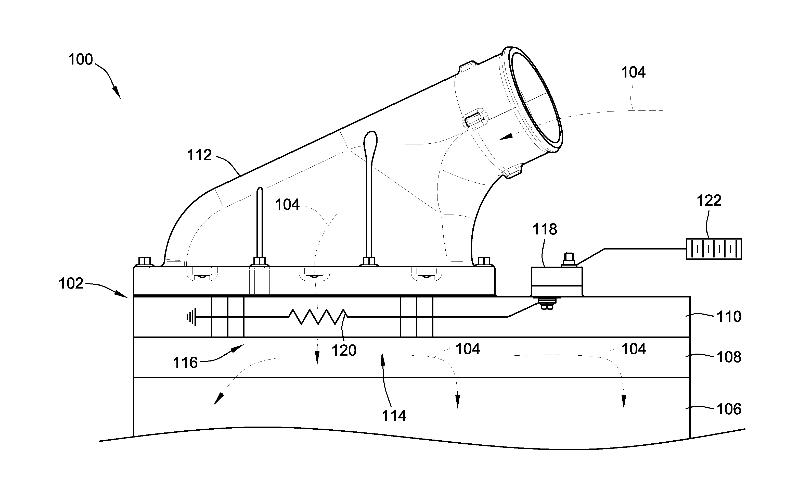
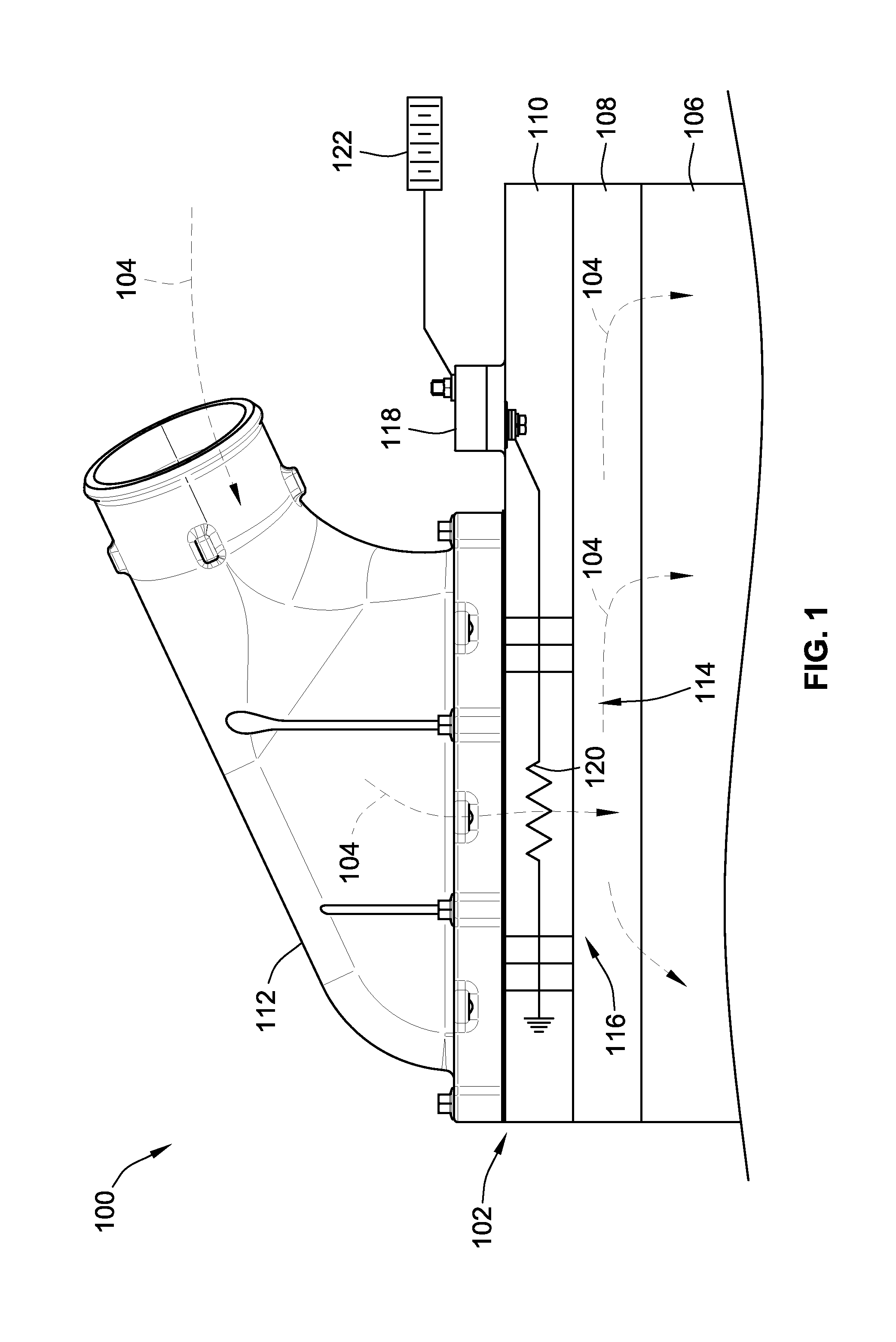
[0108]FIG. 1 is a schematic representation of an engine system 100 in accord with an embodiment of the present invention. The engine system 100 generally includes an air intake system 102 for supplying air to be combusted when combined with fuel. The air intake system 102 draws air from an air supply such as the ambient air supply. Air flow through the air intake system 102 is represented by arrows 104.

[0109]Illustrated in simplified form, the engine system 100 includes a plurality of internal combustion engine components. For instance, the engine system 100 includes an engine block 106, an air intake manifold 108, an intake manifold cover 110 and an air intake supply conduit 112.

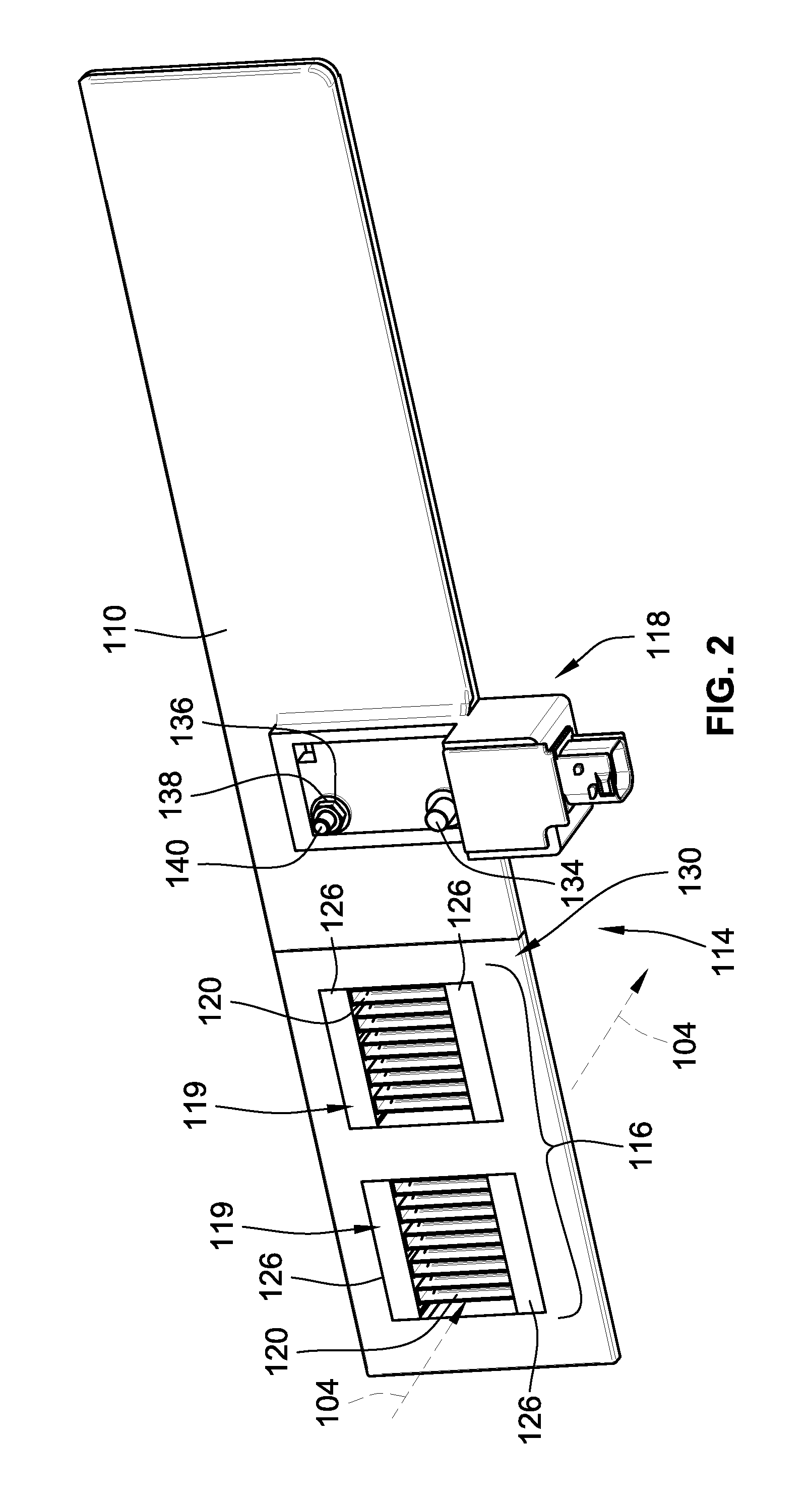
[0110]Within the air intake system 102 is an air heater system 114 positioned in the air flow (represented by arrows 104) passes through an air heater 116 of the air heater system 114 to heat the air prior to being combusted. The air heater system 114 includes an electronic control arrangement in the form o...


PUM


Abstract

An air heater for heating intake air for an internal combustion engine is provided. The air heater may have a heating element with improved air flow redirection. The air heater may include a controller that is formed as an integral component with an other component of an internal combustion engine such as an air intake manifold cover. The heater may include thermocouple circuitry for sensing the temperature of the heating element. Methods of calibrating the thermocouple circuitry are also provided. Methods of controlling the air heater while performing engine start are also provided.

Description

FIELD OF THE INVENTION[0001]This invention generally relates to intake heaters for heating intake air for an internal combustion engine.BACKGROUND OF THE INVENTION[0002]Many internal combustion engine systems utilize an air intake heater system to heat the intake air prior to combustion of the intake air with fuel depending on the intake air temperature and the operating conditions of the internal combustion engines:[0003]As internal combustion engine systems become more and more complex, the pathway through which the intake air flows to the cylinders of the internal combustion engine system becomes more complex. Typically, the heating element of prior air intake heater systems did not redirect the flow of air as it traveled through the heating element. Due to the complex air flows and constraints within engine compartments, the location of air heaters may not be optimal such that straight through flow of air may be undesirable.[0004]Electrically powered air intake heater systems ar...

Claims


Application Information

Patent Timeline
IPC IPC(8): F02M31/04F02M35/10
CPCF02M35/10268F02M31/042F02M31/13Y02T10/12
Inventor URSIC, PETERURBAS, JANEZKRAVOS, DEAN
Owner HIDRIA AET
Why Eureka
Try Eureka