Reproducing device
a technology of a recording device and a spherical aberration, which is applied in the detection/correction of digital signals, instruments, recording signal processing, etc., can solve the problems of spherical aberration, amplitude level of information reading signals and/or tracking error signals may be considerably reduced, and the thickness error of several m
- Summary
- Abstract
- Description
- Claims
- Application Information
AI Technical Summary
Benefits of technology
Problems solved by technology
Method used
Image
Examples
embodiment 1
[0031]The following description discusses an embodiment of the present invention with reference to FIGS. 1 through 6. Note that “content,” described in Embodiment 1 and Embodiments 2 through 5 (later described), refers to information which is to be used by a user. Specific examples of the content encompass (i) a static image such as a photograph, (ii) a moving image such as a movie, and (iii) a program.
[0032]
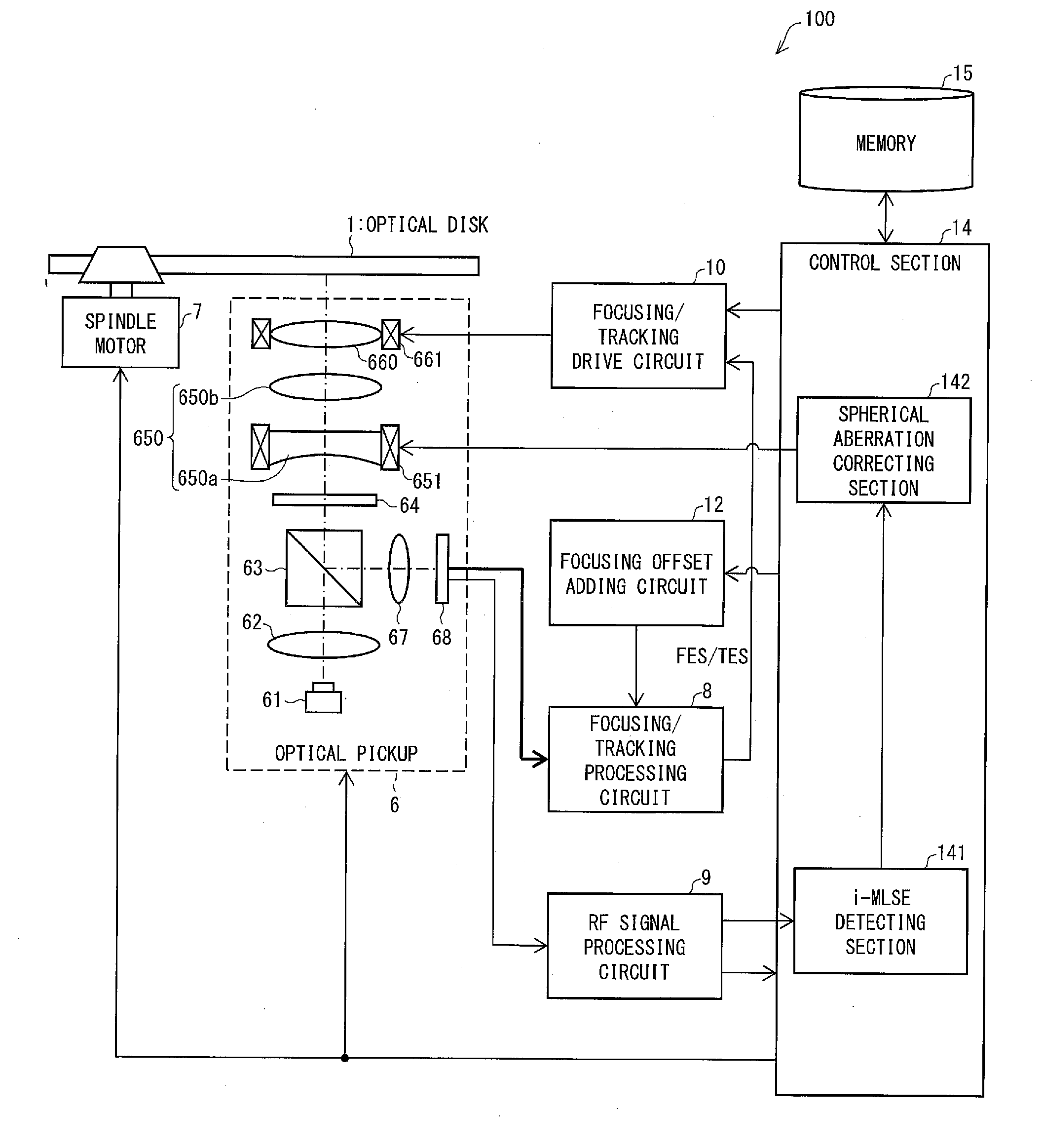
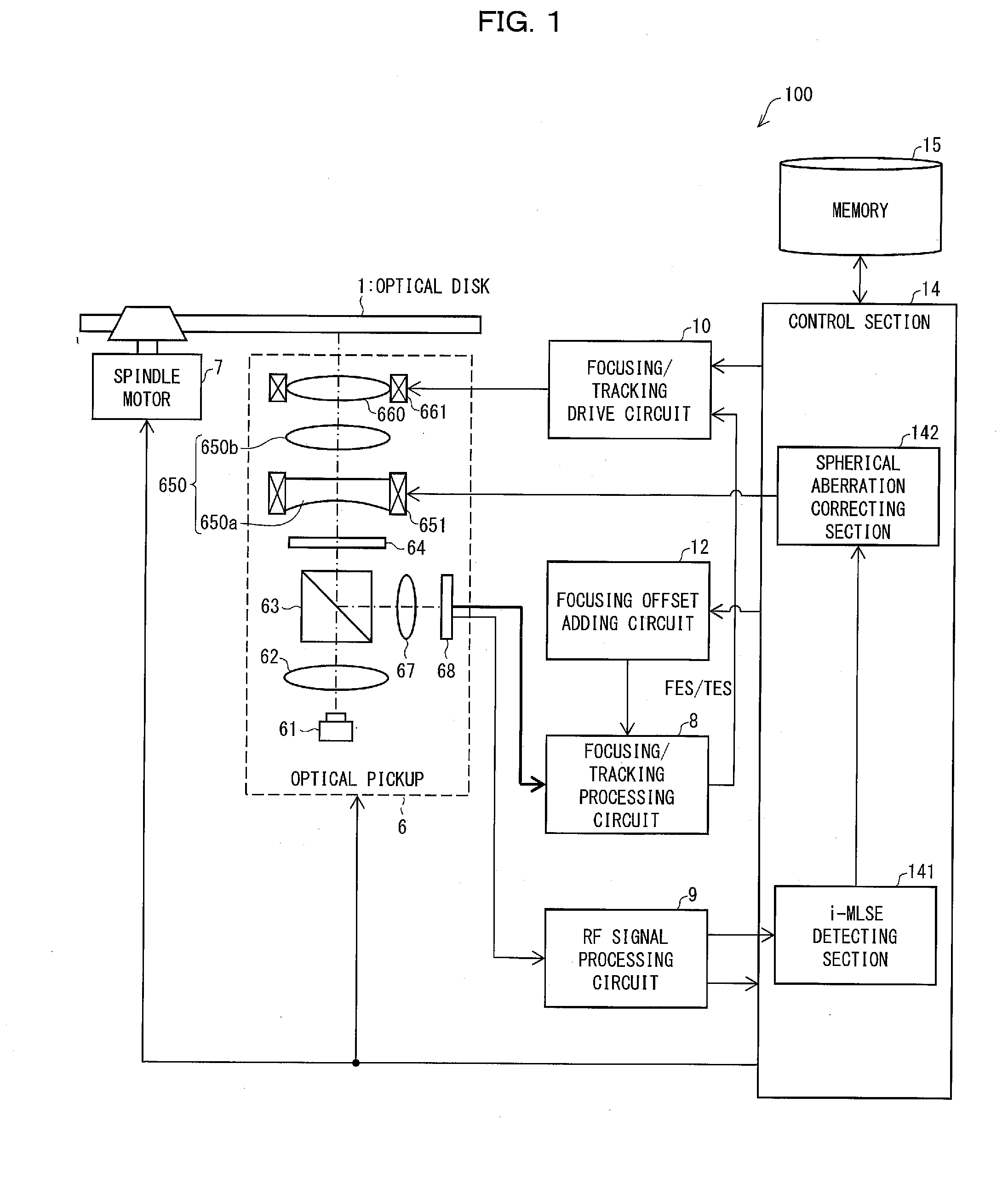
[0033]FIG. 1 is a functional block diagram schematically illustrating a configuration of a reproducing device 100 for reproducing an optical disk 1. The reproducing device 100 includes an optical pickup 6 (irradiation section), a spindle motor 7, a focusing / tracking processing circuit 8, an RF (Radio Frequency) signal processing circuit 9 (conversion section), a focusing / tracking drive circuit 10, a focusing offset adder circuit 12, a control section 14, and a memory 15.
[0034]The optical disk 1 is a read-only optical information recording medium (see FIG. 4 (later described)). I...
experiment 1
[0088]An i-MLSE of each of the optical disks A and B was measured while changing a spherical aberration correcting value.
[0089]That is, Experiment 1 was carried out by use of (i) a BD evaluation system (DDU-1000 (manufactured by Pulstec Industrial Co., Ltd.) / reproducing optical system: reproduction light wavelength (A) 405 nm, numerical aperture (NA) 0.85) and (ii) a BD evaluation signal detector (SD3) manufactured by Pulstec Industrial Co., Ltd. By use of the BD evaluation system and the BD evaluation signal detector, (i) a reproduction power and a reproduction speed were fixed to 1.0 mW and 7.38 m / s, respectively and (ii) a set value for spherical aberration correcting (i.e., an initial value of the spherical aberration correcting value) which set value corresponds to 100 μm, which is the thickness of the light transmitting layer, was set to 0 μm. An i-MLSE was then measured by changing the spherical aberration correcting value.
experiment 2
[0090]Amplitudes of RF signals of the respective optical disks A and B were measured while changing the spherical aberration correcting value.
[0091]Experiment 2 was carried out by use of the devices and the experimental conditions which are similar to those used in Experiment 1.
[0092]
[0093]The following description discusses, with reference to (a) and (b) of FIG. 6, results of the experiments for demonstration which have been carried out with respect to the optical disks A and B.
[0094](b) of FIG. 6 is a graph showing (i) a relationship between the spherical aberration correcting value and the i-MLSE and (ii) a relationship between the spherical aberration correcting value and the amplitude of the RF signal, which relationships were obtained as results of the experiments for demonstration which have been carried out with respect to the optical disk B. In (b) of FIG. 6, a spherical aberration correcting value obtained when the i-MLSE becomes minimum coincides with a spherical aberrati...
PUM
| Property | Measurement | Unit |
|---|---|---|
| wavelength | aaaaa | aaaaa |
| thickness | aaaaa | aaaaa |
| thickness | aaaaa | aaaaa |
Abstract
Description
Claims
Application Information
 - R&D
- Intellectual Property
- Life Sciences
- Materials
- Tech Scout
- Unparalleled Data Quality
- Higher Quality Content
- 60% Fewer Hallucinations
Browse by: Latest US Patents, China's latest patents, Technical Efficacy Thesaurus, Application Domain, Technology Topic, Popular Technical Reports.
© 2025 PatSnap. All rights reserved.Legal|Privacy policy|Modern Slavery Act Transparency Statement|Sitemap|About US| Contact US: help@patsnap.com


