Flexible battery and electronic device

a technology of flexible storage and electronic devices, applied in the direction of batteries, cell components, sustainable manufacturing/processing, etc., can solve the problems of affecting the operation of the storage battery, etc., to achieve the effect of easy breakage, high safety, and easy breakag

Active Publication Date: 2016-06-02
SEMICON ENERGY LAB CO LTD
View PDF2 Cites 21 Cited by
  • Summary
  • Abstract
  • Description
  • Claims
  • Application Information

AI Technical Summary

Benefits of technology

[0017]In one embodiment of the present invention, a wiring that is more easily breakable than a component that is to get fatigued (to be damaged) is provided along the component so that the wiring is changed in form in accordance with a change in the form of the component. Thus, not only the component but also the wiring becomes fatigued (is damaged) by deformation. Fatigue (damage to) accumulated in the component is similar to that accumulated in the wiring; however, the wiring is damaged earlier than the component since the wiring is more easily breakable than the component.
[0018]Thus, a circuit connected to the wiring is configured to detect damage to the wiring. In this case, when the circuit detects damage to the wiring due to fatigue (damage), the use of a storage battery or an electronic device can be stopped. Here, the component in con

Problems solved by technology

As the number of times a flexible lithium-ion storage battery is changed in form increases, fatigue of (damage to) an exterior body thereof holding components and an electrolytic solution of the battery accumulates.
Accumulation of fatigue (damage) might break the exterior body or a sealed structure, resulting in entry of air into the storage battery.
Furthermore, fatigue might build at a tab electrode (terminal portion) of each of a positive electrode and a negative electrode of the storage battery, which breaks the term

Method used


Image

  • Flexible battery and electronic device
  • Flexible battery and electronic device
  • Flexible battery and electronic device

Examples


embodiment 1

[0053]In this embodiment, a lithium-ion storage battery of one embodiment of the present invention will be described.

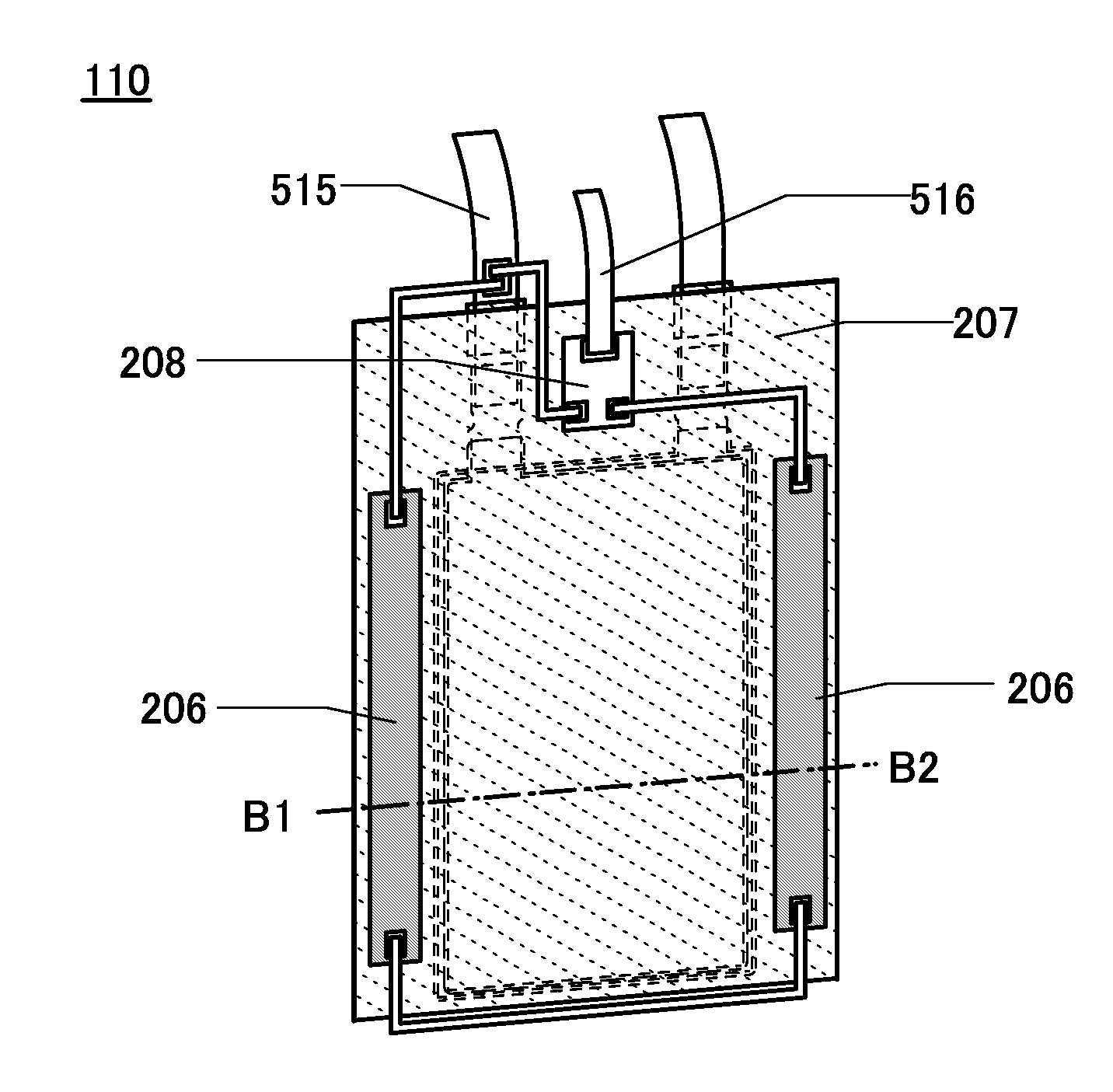
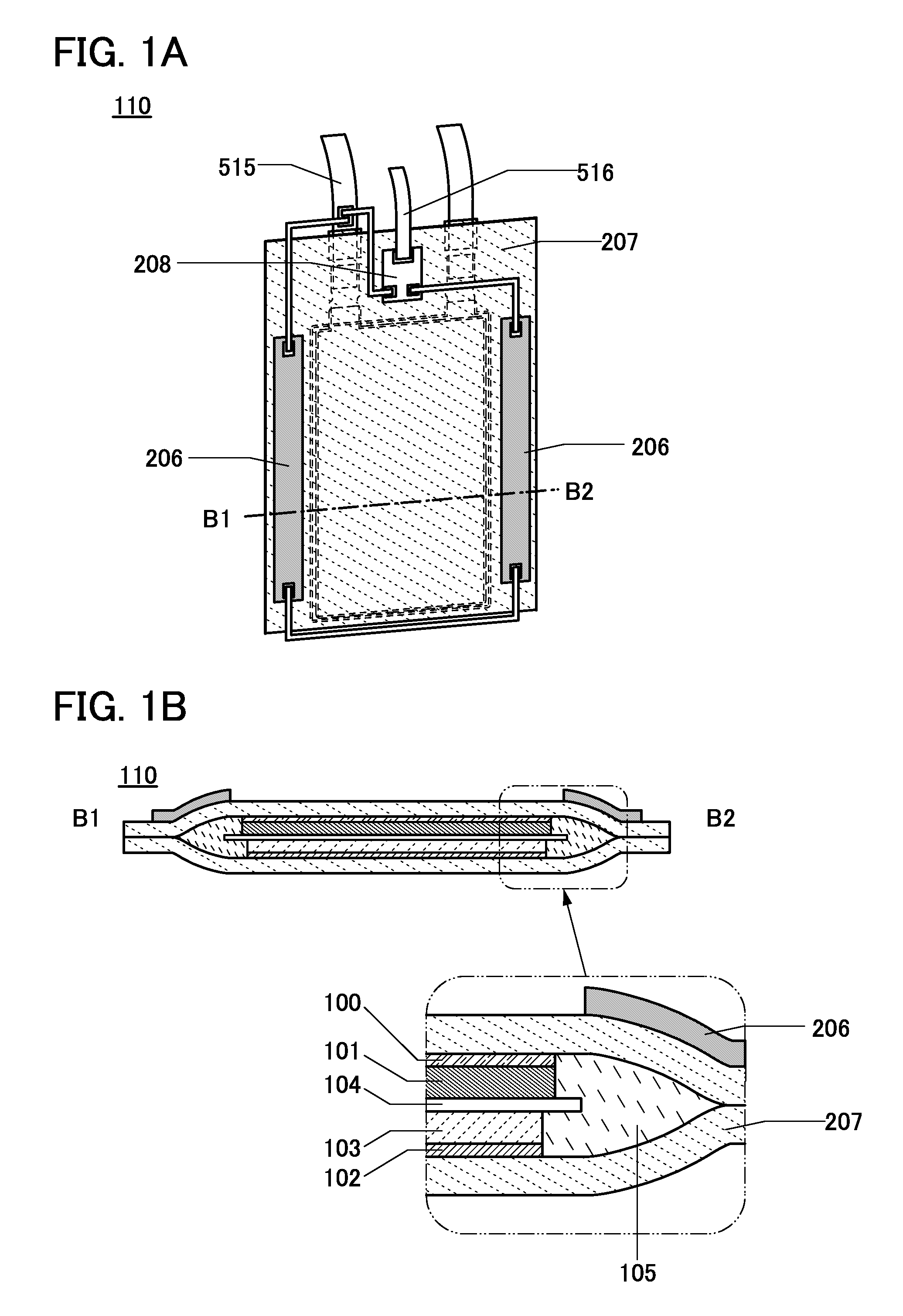
[0054]A method for fabricating a lithium-ion storage battery 110 of one embodiment of the present invention will be described below using FIGS. 1A and 1B. FIG. 1B is a cross-sectional view of the lithium-ion storage battery 110. In the schematic cross-sectional view, a positive electrode current collector 100, a positive electrode active material layer 101, a separator 104, a negative electrode active material layer 103, and a negative electrode current collector 102 are stacked and enclosed together with an electrolytic solution 105 by an exterior body 207. Note that the active material layers can be formed on both surfaces of the current collector, and the storage battery can have a layered structure. Furthermore, in this embodiment, wirings 206 are provided along the exterior body 207, for example. In addition, a circuit 208 connected to the wirings 206 is provided...

embodiment 2

[0137]In this embodiment, an example of the configuration described in the above embodiment in which an exterior body of a lithium-ion storage battery is provided with wirings and examples of the wirings and a circuit for detecting a fracture of the lithium-ion storage battery will be described.

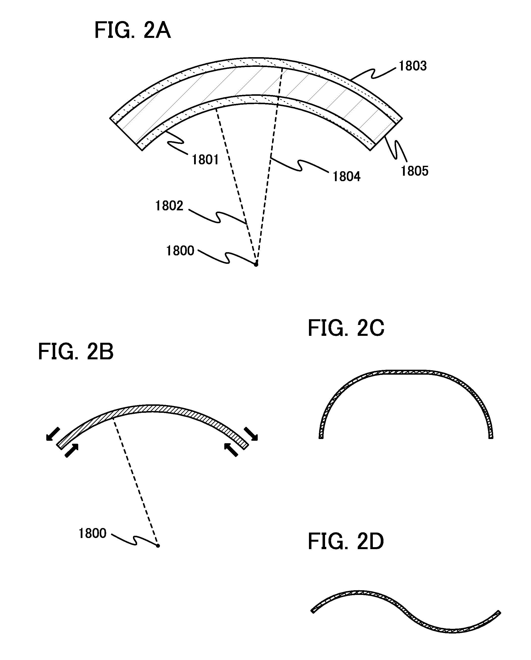
[0138]FIG. 24A is a schematic diagram of a laminated storage battery including an exterior body 5007 that is provided with wirings 5006. FIG. 24B is a cross-sectional view along the dashed-dotted line X1-X2 in FIG. 24A. The exterior body 5007 of the lithium-ion storage battery 110 illustrated in FIGS. 24A and 24B is provided with the wirings 5006 along the shape of the exterior body 5007 in order to prevent damage by fatigue due to deformation. The exterior body 5007 is also provided with a circuit 5008 for detecting damage to the wirings 5006, such as a fracture.

[0139]The wirings 5006 can be formed using a material that is less resistant to deformation than a material of a component to be pr...

embodiment 3

[0156]In this embodiment, structures of a storage batteries of embodiments of the present invention will be described with reference to FIGS. 4A to 4C, FIGS. 5A and 5B, and FIGS. 6A and 6B.

>

[0157]FIG. 4A is an external view of a coin-type (single-layer flat type) storage battery, and FIG. 4B is a cross-sectional view thereof.

[0158]In a coin-type storage battery 300, a positive electrode can 301 doubling as a positive electrode terminal and a negative electrode can 302 doubling as a negative electrode terminal are insulated from each other and sealed by a gasket 303 made of polypropylene or the like. A positive electrode 304 includes a positive electrode current collector 305 and a positive electrode active material layer 306 provided in contact with the positive electrode current collector 305. The positive electrode active material layer 306 may further include a binder for increasing adhesion of positive electrode active materials, a conductive additive for increasing the conducti...


PUM


Abstract

To provide a lithium-ion storage battery or electronic device that is flexible and highly safe. One embodiment of the present invention is a flexible storage battery including a positive electrode, a negative electrode, a separator between the positive electrode and the negative electrode, an exterior body that surrounds the positive electrode, the negative electrode, and the separator, and a wiring provided along the exterior body. At least part of the wiring is more easily breakable by deformation than the exterior body. The wiring is more vulnerable to deformation than the exterior body and thus damaged earlier than the exterior body. Damage to the wiring is detected and an alert is sent to a user; thus, the use of the storage battery can be stopped before the exterior body is damaged.

Description

BACKGROUND OF THE INVENTION[0001]1. Field of the Invention[0002]Embodiments of the present invention relate to a flexible storage battery and a flexible electronic device.[0003]Note that one embodiment of the present invention is not limited to the above technical field. The technical field of one embodiment of the invention disclosed in this specification and the like relates to an object, a method, or a manufacturing method. One embodiment of the present invention relates to a process, a machine, manufacture, or a composition of matter. Specifically, examples of the technical field of one embodiment of the present invention disclosed in this specification include a semiconductor device, a display device, a liquid crystal display device, a light-emitting device, a lighting device, a storage battery, a storage device, a method for driving any of them, and a method for manufacturing any of them.[0004]2. Description of the Related Art[0005]In recent years, a variety of storage batteri...

Claims


Application Information

Patent Timeline
IPC IPC(8): H01M10/42H01M2/02H01M10/0525H01M10/48H01M50/119H01M50/121H01M50/129
CPCH01M10/425H01M10/488H01M2220/30H01M2/0275H01M10/0525H01M10/48Y02E60/10H01M50/124Y02P70/50H01M50/121H01M50/129H01M50/119H01M50/105
Inventor YAMAKAJI, MASAKIMOMO, JUNPEITAJIMA, RYOTAKASAHARA, TAKAHIRO
Owner SEMICON ENERGY LAB CO LTD
Why Eureka
Try Eureka