

Rotor and method of manufacturing same
- Summary
- Abstract
- Description
- Claims
- Application Information
AI Technical Summary
Benefits of technology
Problems solved by technology
Method used
Image

Examples
first embodiment
[0066]Hereinafter, a motor will be described with reference to FIGS. 2 to 5.
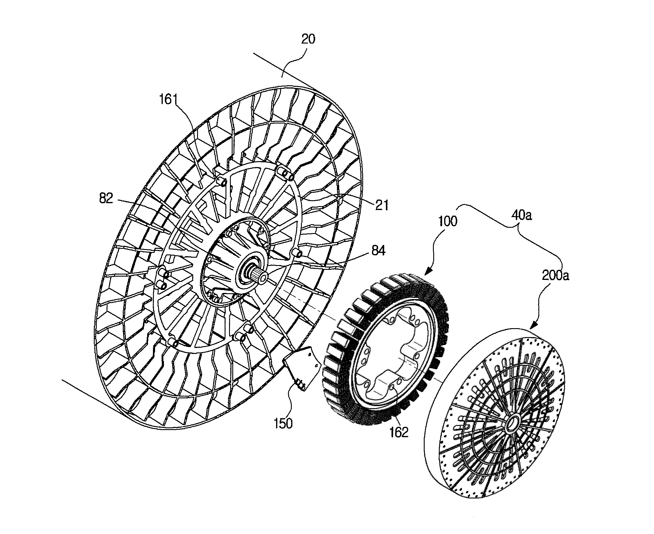
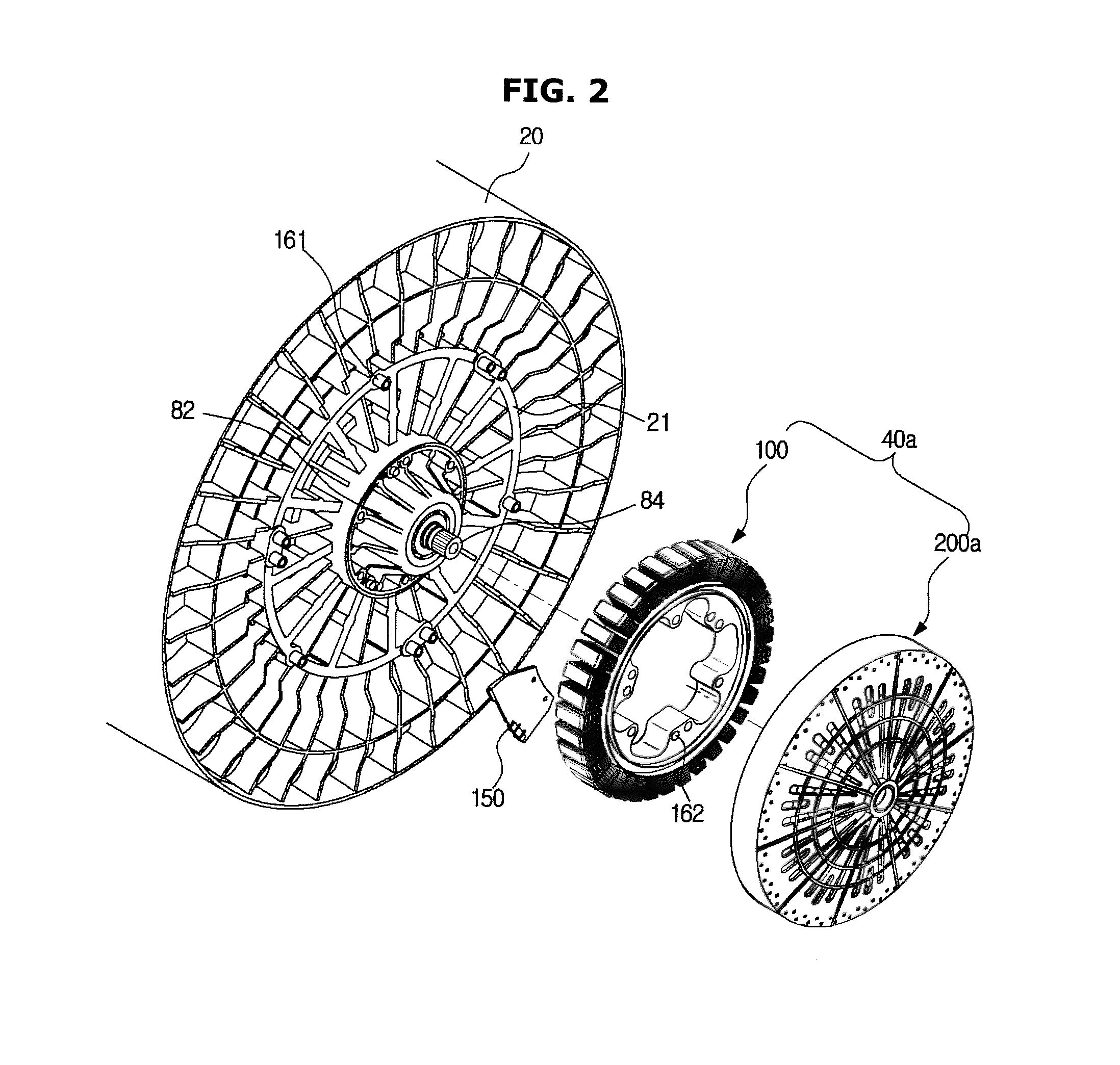
[0067]FIG. 2 illustrates an exploded appearance of a tub and a motor.
[0068]A motor 40a is connected to the rear wall 21 of the tub 20 together with a sensor assembly 150.
[0069]Specifically, the bearings 84 may be disposed at the center of the rear wall 21 of the tub 20, and the bearing housing 82 having the same center point as the bearings 84 and a larger diameter than the bearings 84 may be disposed at the outer circumferential side of the bearings 84. Also, a circular motor mounting unit having the same center point as the bearing housing 82 and a larger diameter than the bearing housing 82 may be disposed at the outer circumferential side of the bearing housing 82. Also, connection protrusions 161 may be disposed along the outer circumference of the circular motor mounting unit.
[0070]At least one connection protrusion 161 may be disposed at the outer circumference of the motor mounting unit, and the conn...
second embodiment
[0132]Hereinafter, a motor will be described with reference to FIGS. 6 to 9.
[0133]FIG. 6 illustrates an exploded view of a tub and a motor.
[0134]The motor 40b is connected to the rear wall 21 of the tub 20 together with the sensor assembly 150.
[0135]The tub 20 and the sensor assembly 150 according to the second embodiment may be the same as or different from the tub 20 and the sensor assembly 150 according to the first embodiment.
[0136]The motor 40b is connected to the motor mounting unit provided at the rear wall 21 of the tub 20, and the motor 40b may include the stator 100 and the rotor 200b.
[0137]The motor 40b applied to the second embodiment will be described in detail with reference to FIGS. 7 to 9.
[0138]FIG. 7 illustrates an exploded view of the motor.
[0139]The motor 40b may include the stator 100 and the rotor 200b.
[0140]The stator 100 may include the stator core 130, the coil 120, and the connection holes 162.
[0141]The stator core 130 forms a frame of the stator 100 to ma...
third embodiment
[0263]Hereinafter, a motor will be described with reference to FIGS. 23 and 24.
[0264]FIG. 23 illustrates a concept of a rotor, and FIG. 24 illustrates a cross-section of the rotor.
[0265]The rotor 200c may include the ring-shaped rotor assembly 210 and a molding unit 260c supporting the rotor assembly 210.
[0266]The rotor assembly 210 forms the magnetic field due to the magnets 240, and allows the attractive force and the repulsive force to act with the magnetic field formed due to the power supplied to the coil 120. Also, the rotor assembly 210 has a ring shape.
[0267]The rotor assembly 210 may include the rotor cores 220 disposed in a radial shape and the magnets 240 disposed between the rotor cores 220.
[0268]The rotor cores 220 and the magnets 240 in the third embodiment may be the same as the rotor cores 220 and the magnets 240 in the first embodiment except directions of the rotor cores 220.
[0269]Specifically, the rotor 200a in the first embodiment is an outer type rotor, but the ...
PUM
 Abstract
Description
Claims
Application Information