Power collection device for electric machine

a technology for power collection and electric machines, which is applied in the direction of dynamo-electric machines, electrical apparatus, windings, etc., can solve the problems of increasing the volume of the isg, easy loosening of rivets, and complicated fabrication process of bonding methods, so as to facilitate the reduction of stress experienced by the connecting member, increase the contact area, and facilitate the effect of processing convenien

Inactive Publication Date: 2016-06-02
IND TECH RES INST
View PDF9 Cites 0 Cited by
  • Summary
  • Abstract
  • Description
  • Claims
  • Application Information

AI Technical Summary

Benefits of technology

[0011]The first groove facilitates to reduce stresses experienced by the connecting member and allows applied stresses to change the configuration of the connection portion wrapping copper wires so as to increase the contact area between the connecting member and the copper wires. As such, the copper wires are firmly secured in the connecting member and the processing convenience is increased.

Problems solved by technology

However, the rivet bonding method complicates the fabrication process and increases the volume of the ISG.
Further, the rivets easily come loose.
As such, the fabrication cost is increased and the product reliability is reduced.

Method used


Image

  • Power collection device for electric machine
  • Power collection device for electric machine
  • Power collection device for electric machine

Examples


Embodiment Construction

[0021]The following illustrative embodiments are provided to illustrate the present disclosure, these and other advantages and effects can be apparent to those in the art after reading this specification. It should be noted that all the drawings are not intended to limit the present disclosure. Various modifications and variations can be made without departing from the spirit of the present disclosure.

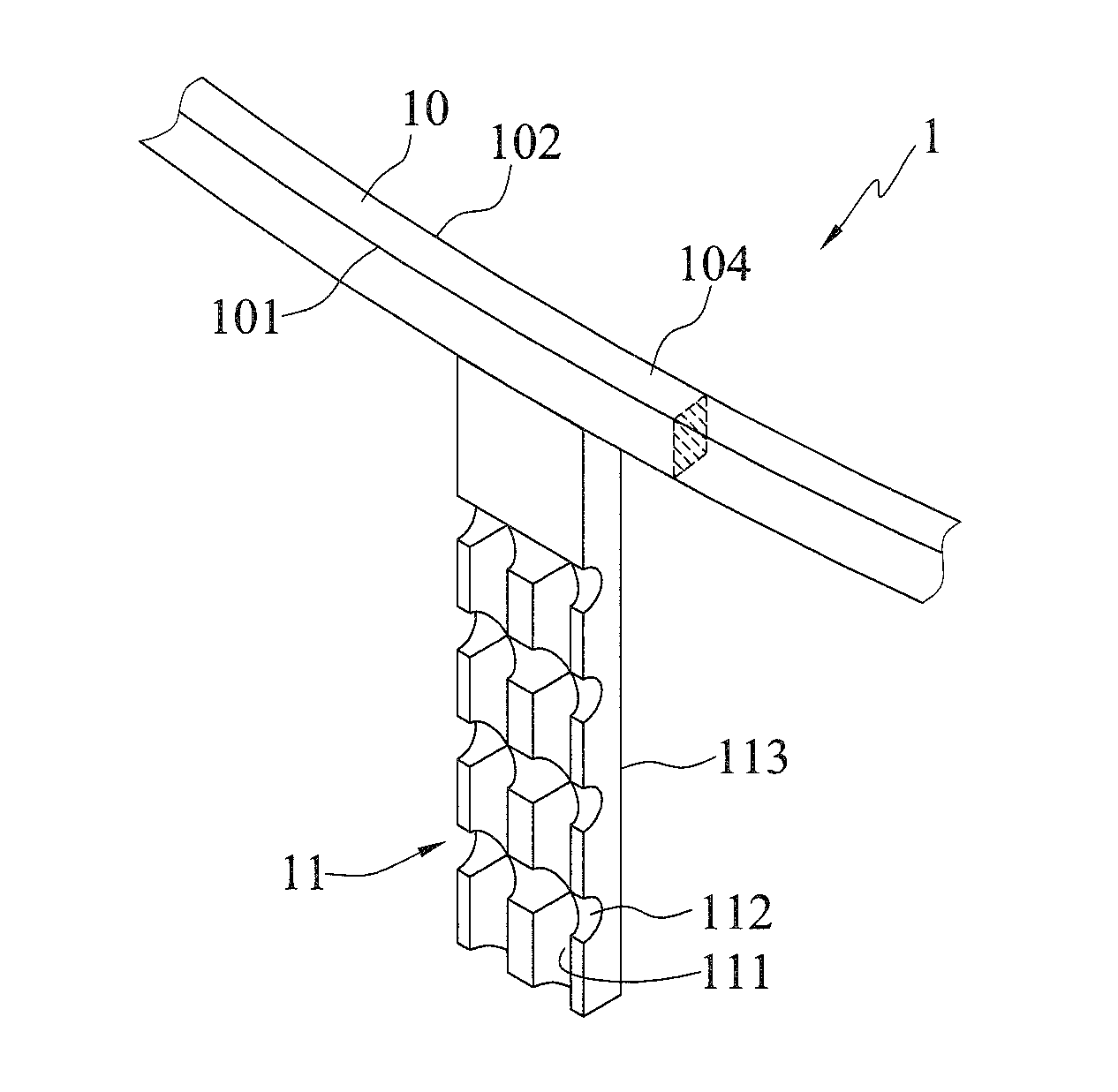
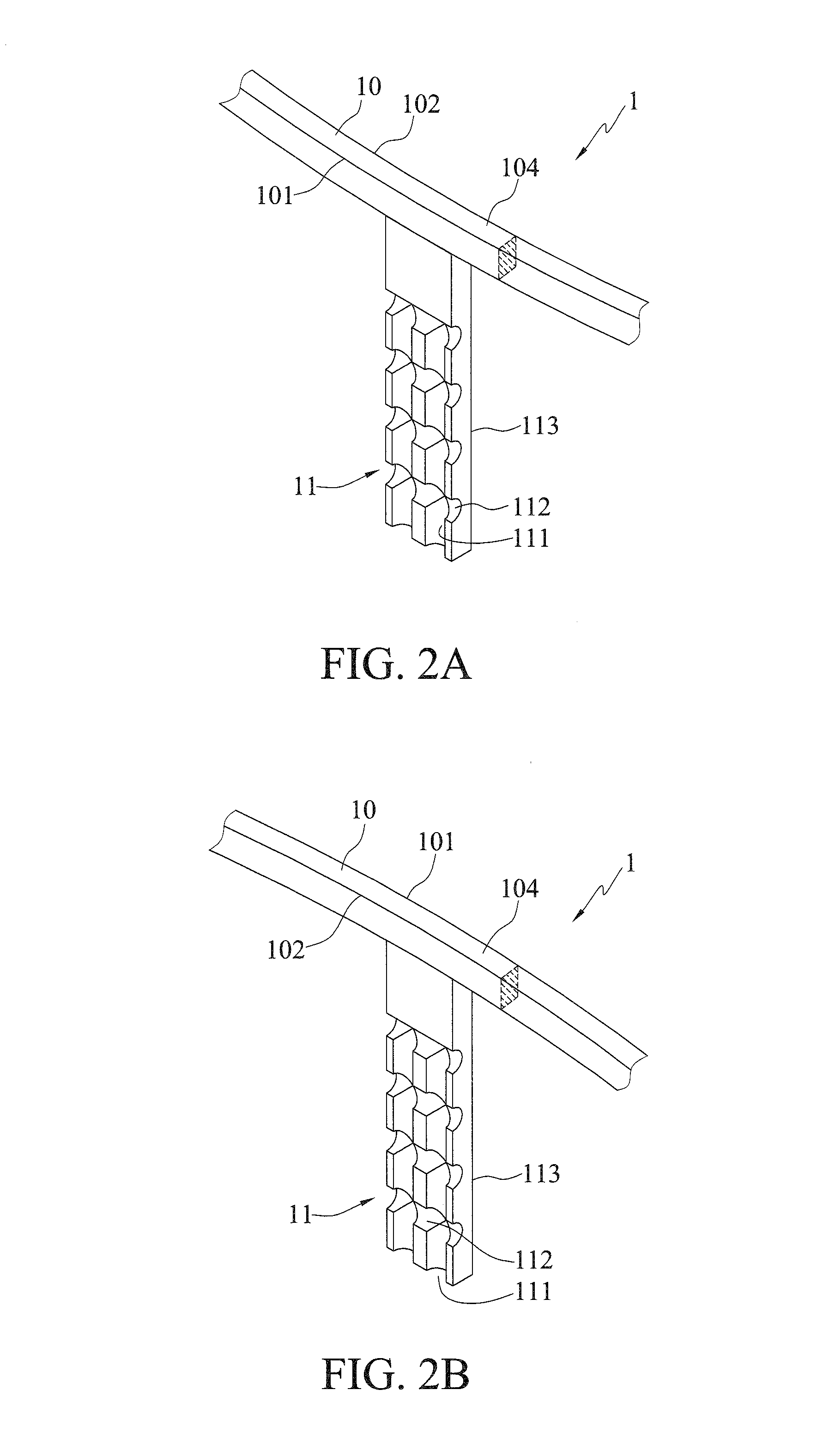
[0022]FIG. 2A is a schematic partial view of a power collection device 1 for an electric machine according to a first embodiment of the present disclosure, and FIG. 2B is a schematic partial view of the power collection device 1 for an electric machine according to a second embodiment of the present disclosure.

[0023]The power collection device 1 has a carrier 10 and a connecting member 11. The carrier 10 is of a ring shape, which has an outer diameter 101, an inner diameter 102, a first surface 103 and a second surface 104 (as shown in FIG. 3). The connecting member 11 protrudes outwar...


PUM


Abstract

A power collection device for an electric machine is provided, which includes: a carrier having a first surface, and a connecting member protruding outward from the first surface of the carrier and having at least a first groove. The first groove facilitates to reduce stresses experienced by the connecting member and allows applied stresses to change the configuration of the connection portion so as to increase the contact area between the connecting member and an object held in the connecting member. As such, the object is firmly secured in the connecting member and the processing convenience is increased.

Description

CROSS REFERENCE TO RELATED APPLICATION[0001]This application also claims priority to Taiwan Patent Application No. 103141749 filed in the Taiwan Patent Office on Dec. 2, 2014, the entire content of which is incorporated herein by reference.BACKGROUND[0002]1. Technical Field[0003]The present disclosure relates to power collection devices for electric machines, and more particularly, to a power collection device for improving the fixing effect.[0004]2. Description of Related Art[0005]FIG. 1A is a schematic view of a conventional mild hybrid propulsion system. Referring to FIG. 1A, an integrated starter-generator (ISG) 7 is disposed between an engine 4 and a transmission 5. To apply the mild hybrid propulsion system in a vehicle, the ISG is designed to have a minimized size so as to save space in the vehicle.[0006]FIG. 1B is a schematic partial view of the ISG 7. Referring to FIGS. 1A and 1B, the ISG 7 has a stator 2 and a power collection device 9 disposed around the stator 2. Copper ...

Claims


Application Information

Patent Timeline
Patent Type & Authority Applications(United States)
IPC IPC(8): H02K3/28
CPCH02K3/28H02K3/522H02K2203/09
Inventor LAN, I-WEIYANG, HAN-PING
Owner IND TECH RES INST
Why Eureka
Try Eureka