Methods and Apparatus for Vision Enhancement

a technology of enhancement system and enhancement apparatus, applied in the field of vision enhancement system and methods, can solve the problems of limiting people's ability to socialize, shop, travel, and socialize, and limiting their ability to travel, so as to facilitate the preservation of the magnified area, enhance the effect of people's image, and prevent any discontinuities

Active Publication Date: 2016-06-02
IRISVISION INC
View PDF5 Cites 58 Cited by
  • Summary
  • Abstract
  • Description
  • Claims
  • Application Information

AI Technical Summary

Benefits of technology

[0010]It is one aspect to provide a device that can present to the user, in real-time, an enhanced video image of a scene surrounding the user so that the user can perform routine tasks. Certain embodiments include: 1) a head-mounted video camera that can obtain an input stream of video images of the scene in front of the user's head; 2) a processor to process the stream of input video images into a stream of output images that corrects for the user's vision deficiencies; and 3) a display for the processed video images that is viewable by the user.
[0011]It is another aspect to provide processed images of a scene that provides a smooth transition between an enhanced portion and an unmagnified peripheral portion. Thus, for example, in one embodiment, the processor performs a remapping of the video images to magnify a central portion of the video images (magnification bubble), to leave the peripheral portion either unmagnified or at a lower power of magnification than the bubble, and to provide a smooth transition between the magnification bubble and the peripheral portion so that the user can easily keep the magnified area within context of the viewed scene.
[0012]It is another aspect that the magnification of the scene varies smoothly across the image to prevent any discontinuities in the processed image and to assure that the remapping by itself does not introduce an additional scotoma or blind area. Thus, for example, the mapping may present an unmagnified image that contains no edges and include a magnified image at some central portion.
[0013]It is yet another aspect to provide a system that enhances images for people with low-vision by mapping each pixel of an imaged scene to an output image viewable by the user of the system. The mapping is performed, in one embodiment, to provide a smoothly varying magnification across the output image such that the user of the system can easily see how the magnified region is part of the peripheral area. Thus, for example, the user of the system can see every part of the original scene without any visual discontinuities.
[0014]It is one aspect to provide a device that can present to the user an enhanced video image of a scene surrounding the user and permit them to modify the enhancement in real-time. Thus the user can modify, for example, one or more attributes of the magnification bubble, including without limitation, the magnifying power, the size of the magnification bubble, the shape of the magnification bubble, the position of the magnification bubble, and contrast and / or light level of the image.

Problems solved by technology

This disability greatly diminishes their quality of life, greatly limiting their ability to socialize, shop, cook, and travel.
Recent technical advances in digital technology have greatly improved the ability to read with large magnified CCTV displays, but mobility still remains a difficult challenge: magnification is effective for static activities like reading or watching TV, but does not enable a person to move through the environment while viewing a magnified view of the environment.
The reason is that magnification of the entire image dramatically reduces the overall field of view.

Method used


Image

  • Methods and Apparatus for Vision Enhancement
  • Methods and Apparatus for Vision Enhancement
  • Methods and Apparatus for Vision Enhancement

Examples


first embodiment

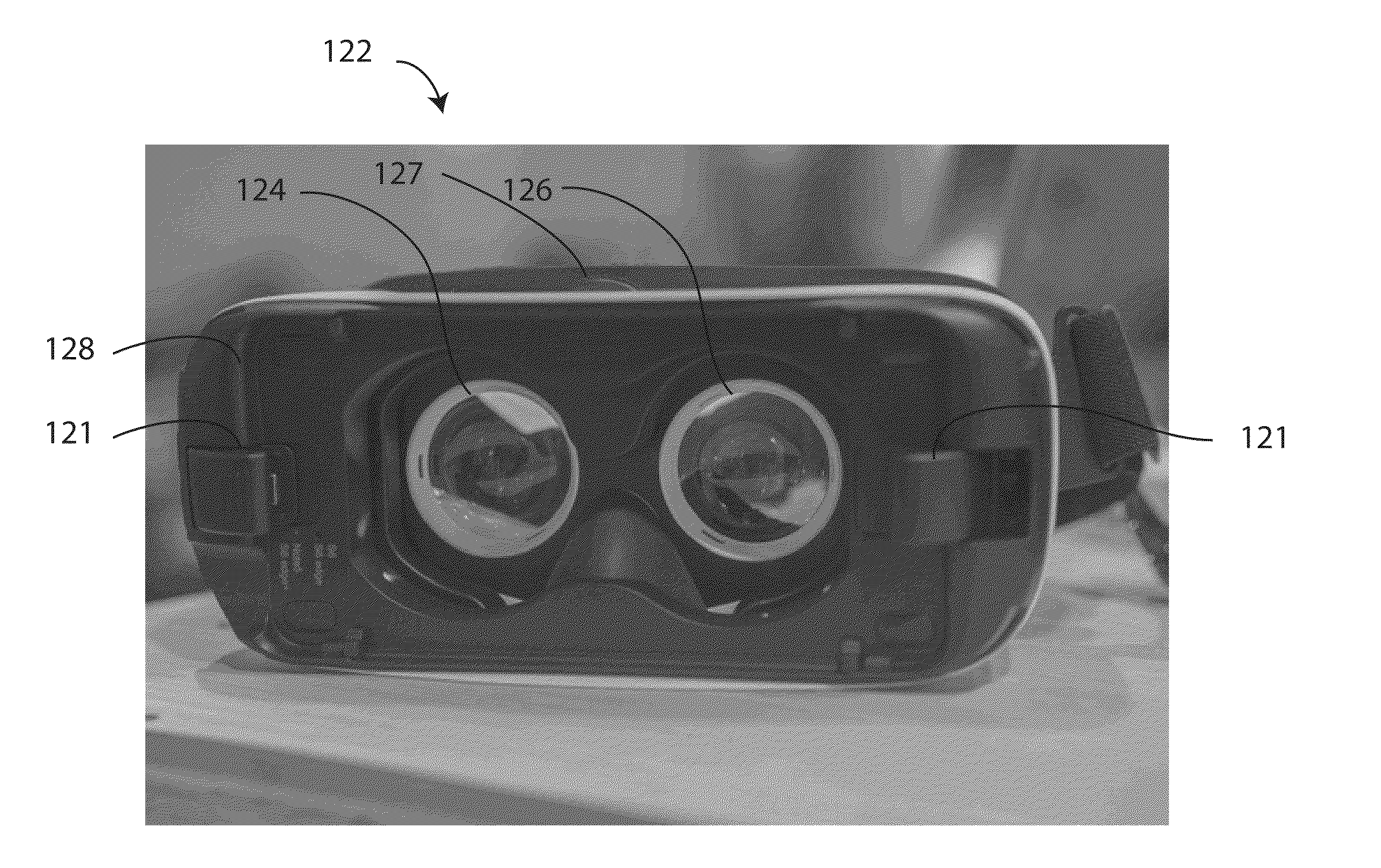
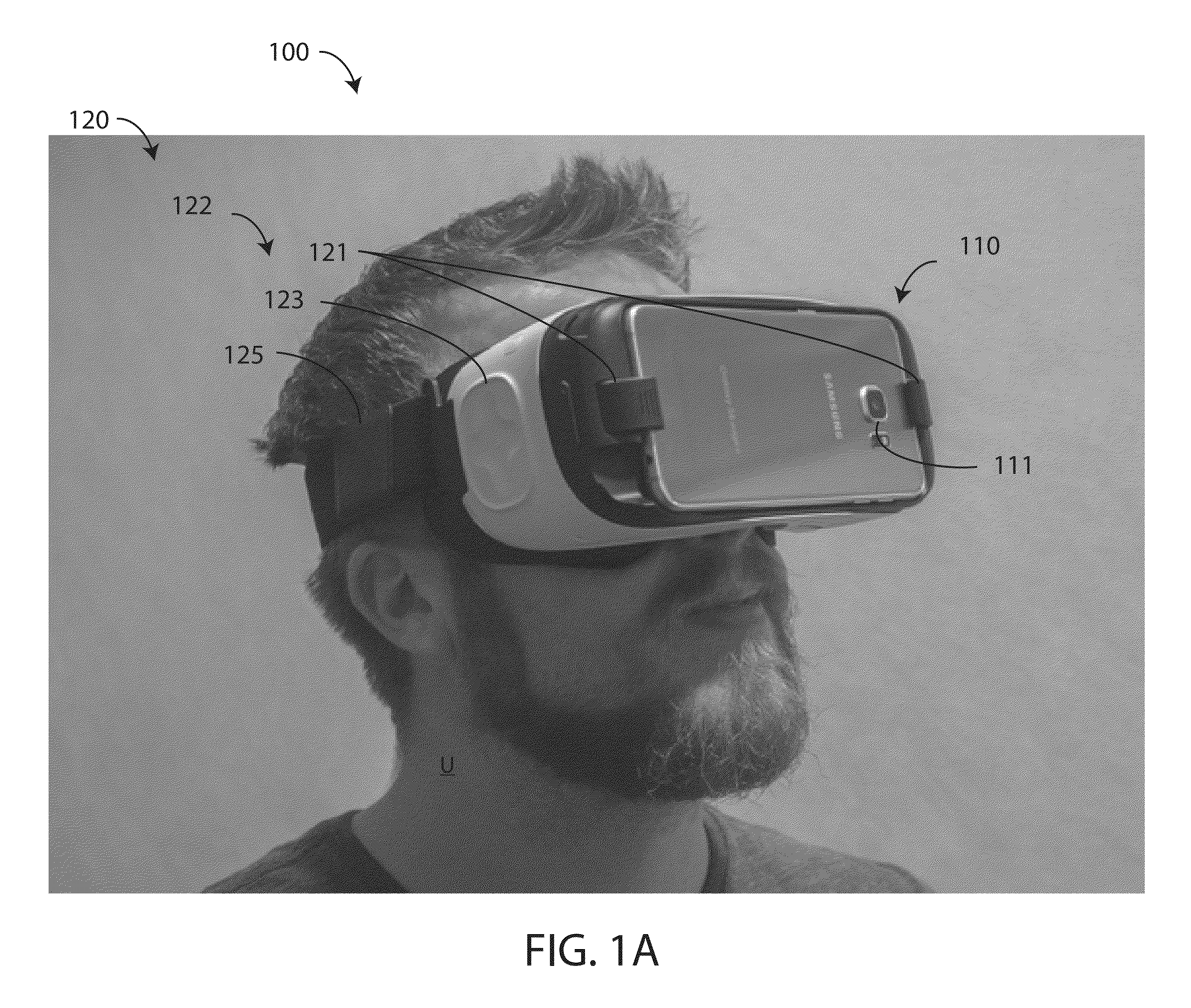
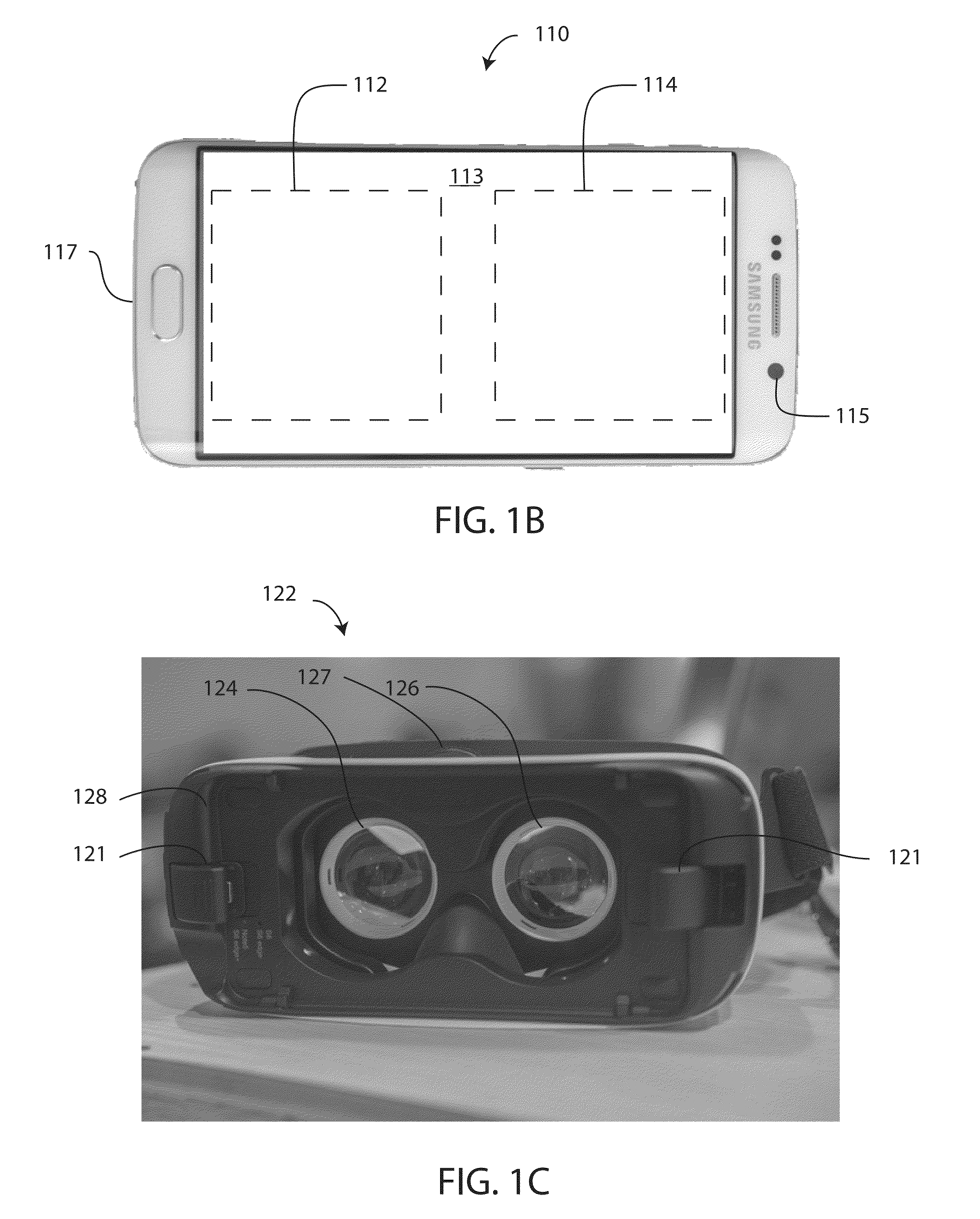
[0034]By way of a specific embodiment, FIGS. 1A, 1B, and 1C shows a first embodiment user-controllable vision-enhancement system 100, where FIG. 1A shows the system on a user, FIG. 1B shows a smartphone used in the system and FIG. 1C shows the body of the goggle used in the system. System 100 includes a smartphone 110 and pair of goggles 120. Smartphone 110 includes the electronics necessary for the vision-enhancement system 100, including a processor and memory (not shown), a forward facing camera 111, as shown in FIG. 1A, and a screen 113 on the side opposite the camera, as shown in FIG. 1B. Smartphone 110 also includes an electrical connector 117 and may also include a backward facing camera 115, which may be used in certain embodiments. As described subsequently, processed camera images are displayed on one portion of screen 113 shown as a left area 112 and a second portion of the screen is shown as right area 114.

[0035]Goggles 120 include a body 122 and a strap 125 for holding ...

second embodiment

[0063]Thus, for example, a user may, through input device 123, modify the transformation to move the magnification bubble within display areas 112 / 114, or change the magnification and / or transition to peak magnification. FIG. 4, for example, shows a second embodiment output image 400, where, relative to output image 300: 1) the region magnified and the magnification bubble are shifted to the right, resulting a different area to be magnified; 2) the radius of second boundary 225 is decreased, resulting in a larger magnification with the same magnification bubble size; and 3) the radius of first boundary 215 is decreased, resulting in a decreased magnification bubble size and a decreased size of the transition from the unmagnified to magnified image portions.

[0064]In certain embodiments, the bubble may be defined mathematically or algorithmically by several variables which may include, but are not limited to: 1) the diameter of the magnification bubble; 2) the peak magnification of th...


PUM


Abstract

A system and methods for the enhancement of a user's vision using a head-mounted and user-controllable device including a magnification bubble having variable attributes wherein a portion of the scene is magnified within the complete scene, wherein the user is able to modify, in real-time, how the images are processed including the attributes of the magnification bubble.

Description

CROSS-REFERENCE TO RELATED APPLICATIONS[0001]This application claims the benefit of U.S. Provisional Application No. 62 / 077,434, filed Nov. 10, 2014, U.S. Provisional Application No. 62 / 131,957 filed Mar. 12, 2015, and U.S. Provisional Application No. 62 / 155,972, filed May 1, 2015, the contents of which are hereby incorporated by reference in their entirety.BACKGROUND OF THE INVENTION[0002]1. Field of the Invention[0003]The present invention generally relates to a vision-enhancement system and methods, and more particularly, to a head-mounted and user-controllable method and system for vision-enhancement, and a system and method for configuring a vision-enhancement system.[0004]2. Discussion of the Background[0005]The normal human visual system establishes a non-magnified representation of a scene in the visual periphery with a high-resolution representation at the center of the visual field. Thus, the cornea and lens of the eye focuses a viewed scene onto the retina, which includes...

Claims


Application Information

Patent Timeline
Patent Type & Authority Applications(United States)
IPC IPC(8): H04N5/232G06F3/01H04N5/77
CPCH04N5/23296G06F3/013H04N5/23216H04N5/77H04N5/772G06F2203/04805G02B27/017G02B2027/0138G02B2027/014
Inventor WERBLIN, FRANK S.MASSOF, ROBERTBOGER, YUVAL S.
Owner IRISVISION INC
Why Eureka
Try Eureka