
Flexible locked plate fixation

a flexible, fixed plate technology, applied in the field of fixed plate devices, can solve the problems of not always desirable absolute rigidity, and achieve the effect of reducing rigidity and rigidity

Inactive Publication Date: 2016-06-09
STRYKER EURO HLDG I LLC
View PDF4 Cites 11 Cited by
  • Summary
  • Abstract
  • Description
  • Claims
  • Application Information

AI Technical Summary

Benefits of technology

This solution promotes bone healing by allowing controlled micromotion along the main axis of the bone, reducing the risk of complications associated with rigid fixation and enhancing the stability of the fracture site during the healing process.

Problems solved by technology

However, absolute rigidity is not always desirable and it can be advantageous when an implantable bone plate is capable of a degree of freedom along the main axis of the bone plate.

Method used


Image

  • Flexible locked plate fixation
  • Flexible locked plate fixation
  • Flexible locked plate fixation

Examples


Embodiment Construction

[0028]As used herein, when referring to bones or other parts of the body, the term “proximal” means closer to the heart and the term “distal” means more distant from the heart. The term “inferior” means toward the feet and the term “superior” means towards the head. The term “anterior” means towards the front part of the body or the face and the term “posterior” means towards the back of the body. The term “medial” means toward the midline of the body and the term “lateral” means away from the midline of the body.

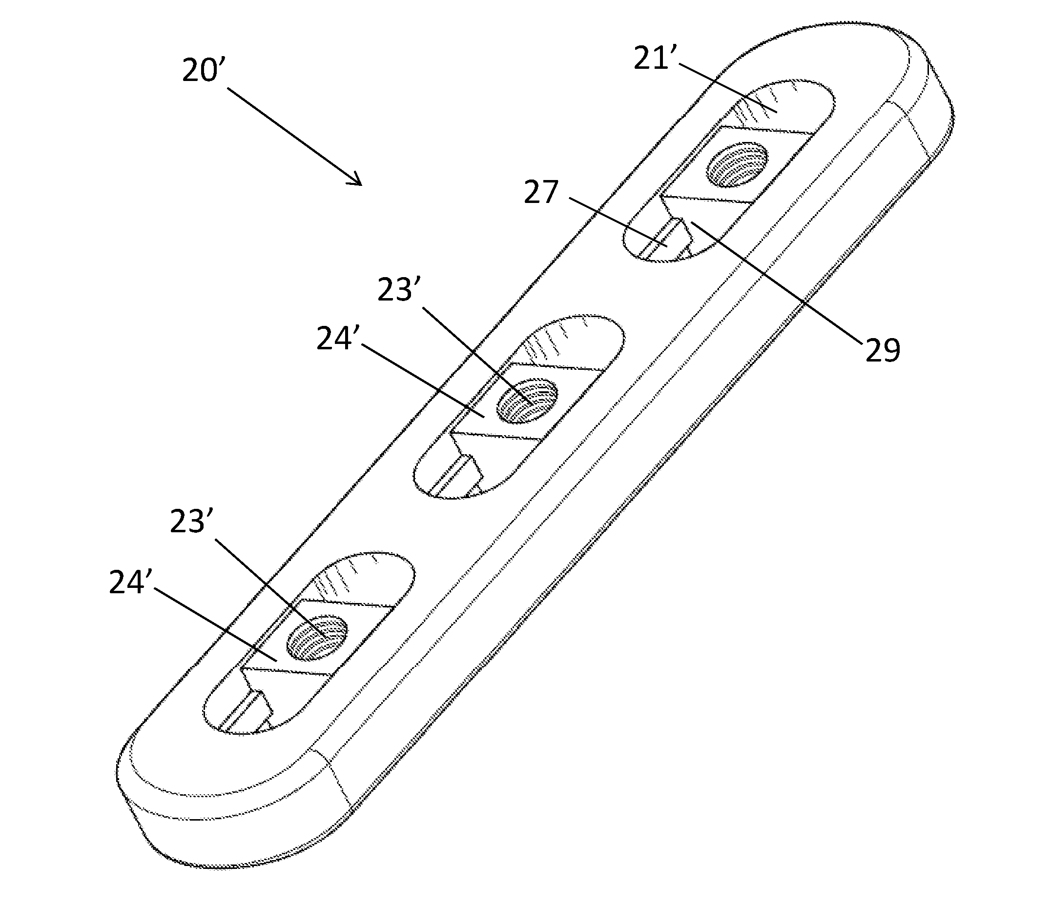
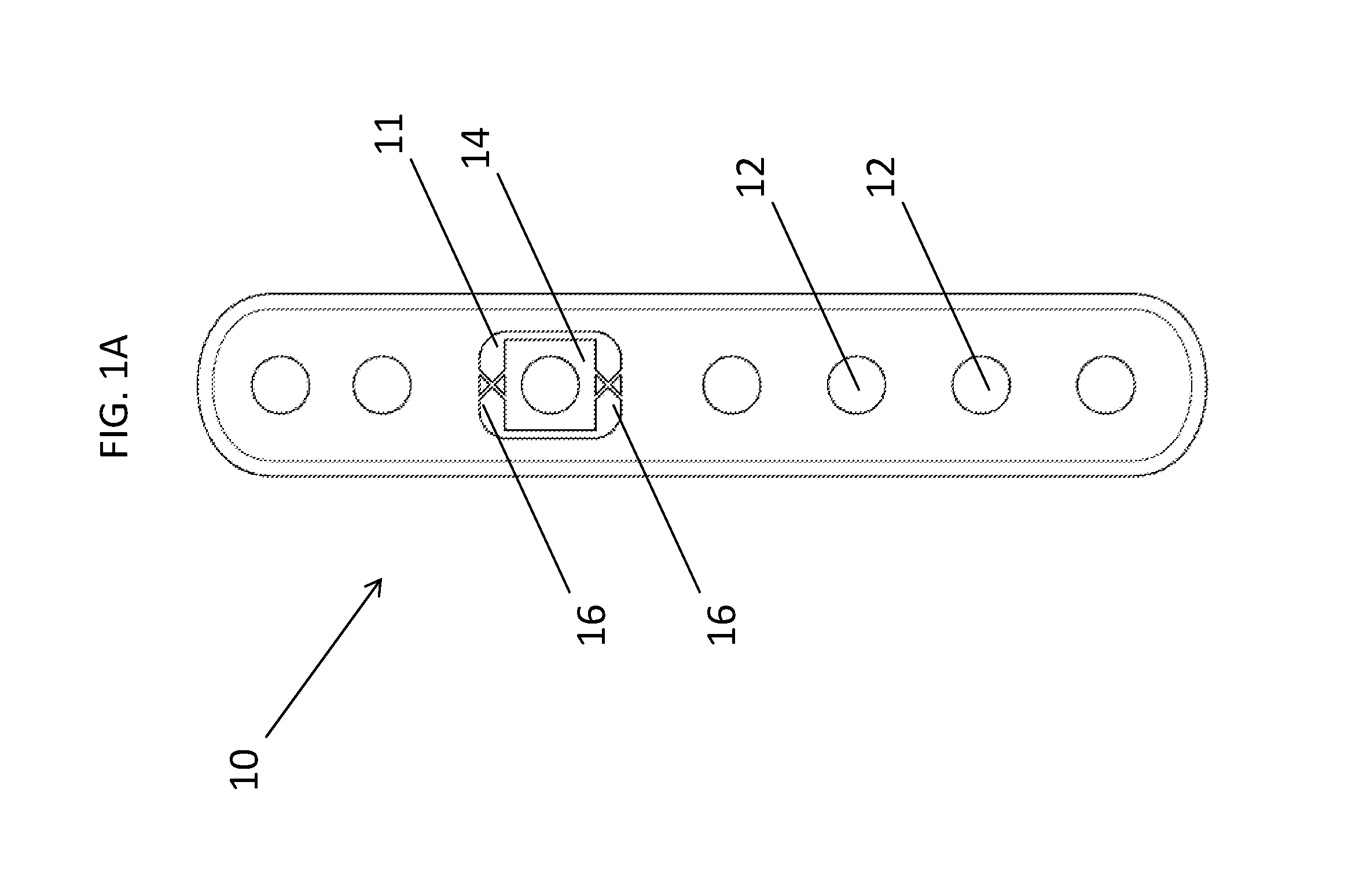
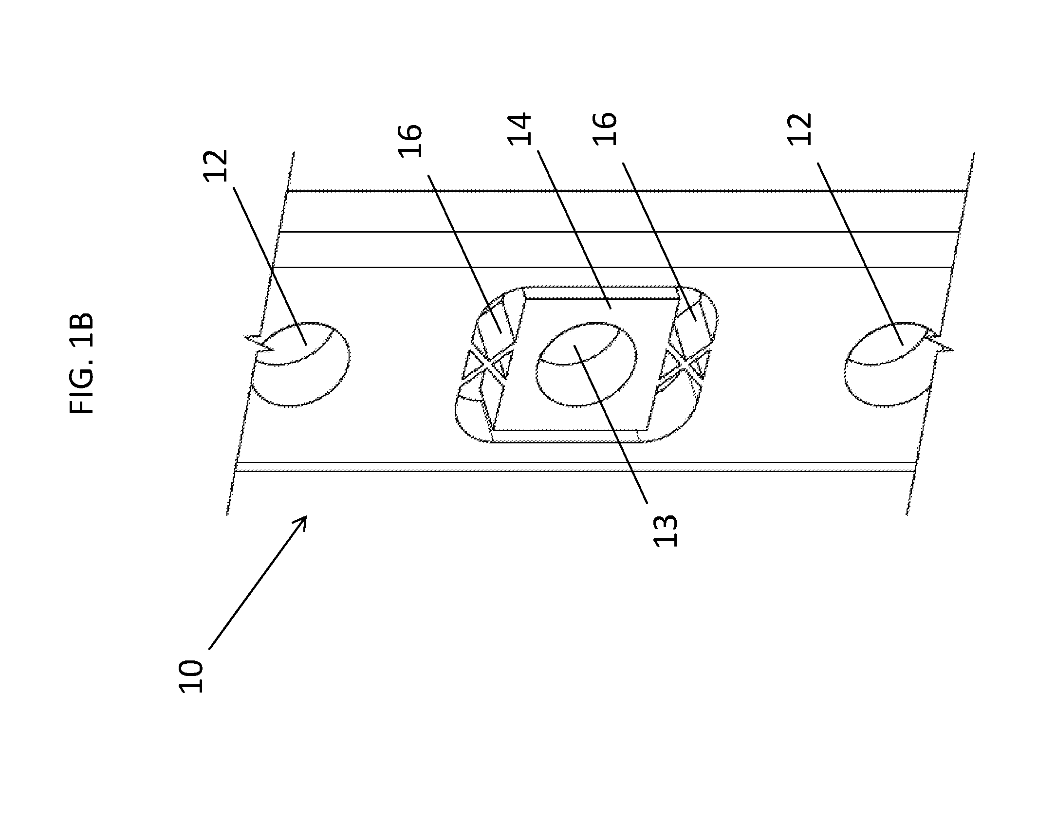
[0029]Referring to FIG. 1A there is shown a top view of one embodiment of bone fixation device10. Bone fixation device 10 includes a bone contacting surface (not shown) and a surface facing away from the bone (shown in FIG. 1) with a plurality of holes or apertures 12 extending between the two surfaces. Holes or apertures 12 may be either threaded (for use with locking screws) or non-threaded (for use with non-locking or compression screws) and may be any suitable shape, su...


PUM


Abstract

A bone fixation device is disclosed that permits some movement of different portions of a fractured bone when the device is affixed thereto. Various embodiments are disclosed, including bone plates that have fixed holes and floating holes therethrough for receiving bone screws, and bone plates including oblong holes allowing for screw movement.

Description

CROSS-REFERENCE TO RELATED APPLICATIONS[0001]The present application claims the benefit of the filing date of U.S. Provisional Patent Application No. 61 / 549,439 filed on Oct. 20, 2011, the disclosure of which is hereby incorporated herein by reference.BACKGROUND OF THE INVENTION[0002]The present invention relates to devices used in the fixation of fractures in bones. More specifically, the present invention relates to a flexible bone plating system that rigidly fixes adjacent ends of a fractured bone while still allowing axial dynamization of the bone to promote healing of the fracture.[0003]Typical fixation of a fracture of a long bone with a bone plate requires making an incision in the tissue, reducing the fracture, placing a bone plate on the fractured bone, and securing the bone plate to the bone with fixation elements such as screws. The bone plate immobilizes the fracture and keeps the bone in a correct position so as to allow the fracture to heal. In certain cases, the bone ...

Claims


Application Information

Patent Timeline
Patent Type & Authority Applications(United States)
IPC IPC(8): A61B17/80
CPCA61B17/8047A61B17/8085A61B17/8004A61B17/8042
Inventor ARELLANO, LUIS A.CHANG, ERIC
Owner STRYKER EURO HLDG I LLC
Learn More