Method and device for ink-jet printing onto containers

Active Publication Date: 2016-06-09
KRONES AG
View PDF1 Cites 6 Cited by
  • Summary
  • Abstract
  • Description
  • Claims
  • Application Information

AI Technical Summary

Benefits of technology

[0025]Alternatively or additionally, the surface velocities can be measured in a contactless manner by optical scanning of the lateral portions and/or by acoustic sensing by way of ultrasound. This is particularly advantageous for large relative velocities between the container surface to be measured and the measuring device and/or a short residence time of the container in t

Problems solved by technology

The problem remains, however, that the dimensional and/or shape tolerances of the container, for example, unwanted eccentricity of the container cross-section, cause print advance rates of different velocities of the surface to be printed on in front of the associated print heads or nozzle rows when rotating the container about itself or when moving it along curved transport paths.
Moreover, connecting regions with overlapping prints or with gaps arise when assembling the partial print images that have been created by use of different print heads or nozzle rows.
When rotating glass bottles with a rotationally-symmetrical nominal cross-section, for example, the container wall laterally impacts due to its eccentricity, which has previously prevented

Method used


Image

  • Method and device for ink-jet printing onto containers
  • Method and device for ink-jet printing onto containers
  • Method and device for ink-jet printing onto containers

Examples


Embodiment Construction

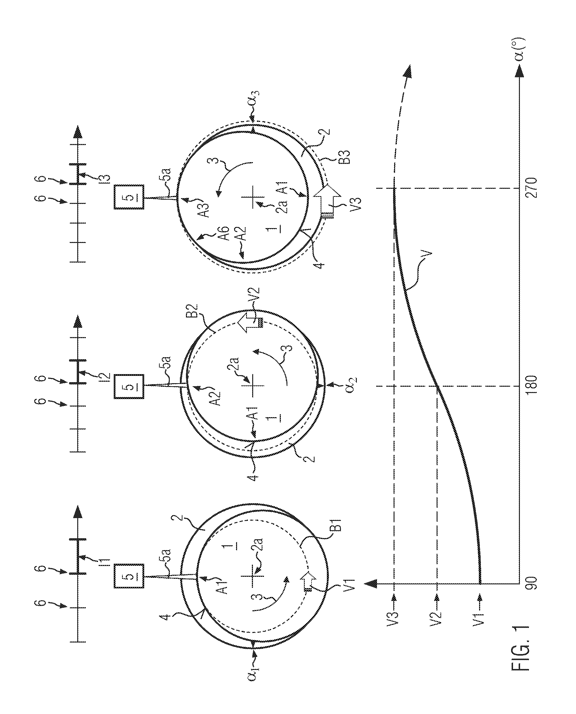
[0044]FIG. 1 schematically shows velocity measurement according to the invention at a container 1 shown in top view which is rotated about itself about an axis of rotation 2a of a positioning unit 2 at an angular velocity 3. Due to an eccentric position and / or shape of a lateral surface 4 of container 1 relative to axis of rotation 2a, partially circumferential portions A1-A3 of lateral surface 4 being denoted by way of example circulate along paths B1-B3 at different surface velocities V1-V3. This is schematically indicated in FIG. 1 by block arrows having different sizes. Associated rotational positions a

[0045]1-α3 of container 1 are marked on positioning unit 2.

[0046]The different surface velocities V1-V3 are caused by the radial distances of lateral portions A1-A3 from rotational axis 2a. In the example shown, lateral portion A1 has the smallest radial distance from axis of rotation 2a and lateral portion A3 has the largest radial distance. Different radial distances of lateral ...


PUM

PropertyMeasurementUnit
Timeaaaaaaaaaa
Angular velocityaaaaaaaaaa
Velocityaaaaaaaaaa

Abstract

A method and a device for ink-jet printing onto containers is described, in which at least one container is rotated and/or transported along a curved path, and associated surface velocities of partially circumferential portions of a lateral container surface are measured, where the printing times and/or a rotational velocity of the containers associated with the partially circumferential and/or intermediately disposed portions are adapted to the surface velocities. Changes in the print advance rate caused by different surface velocities in front of print heads can thereby be compensated This allows for uniform print resolution and seamless joining of partial prints.

Description

CROSS REFERENCE TO RELATED APPLICATIONS[0001]The present application claims priority to German Patent Application No. 102014225256.3, entitled “METHOD AND DEVICE FOR INK-JET PRINTING ONTO CONTAINERS,” filed on Dec. 9, 2014, the entire contents of which are hereby incorporated by reference for all purposes.FIELD OF THE INVENTION[0002]The invention relates to a method and a device for ink-jet printing onto containers.BACKGROUND AND SUMMARY OF THE INVENTION[0003]When directly printing onto containers, such as bottles, a print advance rate of the surface to be printed on relative to at least one ink-jet print module is achieved in that the container is in the region of the print module rotated about itself and / or passed by the print module along a predetermined transport path. A plurality of partial prints is, after setting a suitable rotational orientation of the container and while maintaining a print advance rate as constant as possible, then combined at the respectively associated p...

Claims


Application Information

Patent Timeline
IPC IPC(8): B41J2/045B41J3/407
CPCB41J2/04526B41J2/04586B41J3/4073B41M5/0088B41J3/40733B41P2217/62
Inventor SONNAUER, ANDREAS
Owner KRONES AG
Why Eureka
Try Eureka