
Method for producing carbon fiber bundle and heating furnace for carbon fiber precursor fiber bundle

a technology of carbon fiber and precursor fiber, which is applied in the direction of furnaces, lighting and heating apparatus, drying machines with progressive movements, etc., can solve the problems of uneven temperature and uneven treatment of carbon fiber, and achieve the effects of reducing wind velocity, reducing pressure loss, and easy fabrication, attachment and detachmen

Inactive Publication Date: 2015-07-02
MITSUBISHI CHEM CORP
View PDF2 Cites 2 Cited by
  • Summary
  • Abstract
  • Description
  • Claims
  • Application Information

AI Technical Summary

Benefits of technology

The invention provides a hot wind mixing chamber that can achieve a uniform temperature distribution and equalize heat treatment for a fiber sheet, resulting in a high-quality product. The chamber has a simple structure with a wind direction changing plate, making it easy to fabricate, attach, and detach. This design reduces the cost of the hot wind mixing member and installation.

Problems solved by technology

Currently, in the carbon fiber manufacturing plant in operation, unevenness in treatment is caused to the carbon fiber since there is unevenness in temperature in the width direction in the flameproofing furnace.
In the flameproofing furnace in which a heat treatment chamber to heat-treat the running carbon fiber precursor fiber bundle with hot wind is adjacent to a circulating flow path to circulate the hot wind from the downstream portion of the heat treatment chamber to the upstream portion thereof, the temperature of the hot wind on side of the wall in contact with the outside air is low and the temperature on the wall side where the heat treatment chamber is in contact with the circulating flow path is high, and the hot wind is supplied to the heat treatment chamber while maintaining the temperature distribution even after passing through a blower fan, which causes the unevenness in temperature.

Method used


Image

  • Method for producing carbon fiber bundle and heating furnace for carbon fiber precursor fiber bundle
  • Method for producing carbon fiber bundle and heating furnace for carbon fiber precursor fiber bundle
  • Method for producing carbon fiber bundle and heating furnace for carbon fiber precursor fiber bundle

Examples


example 1

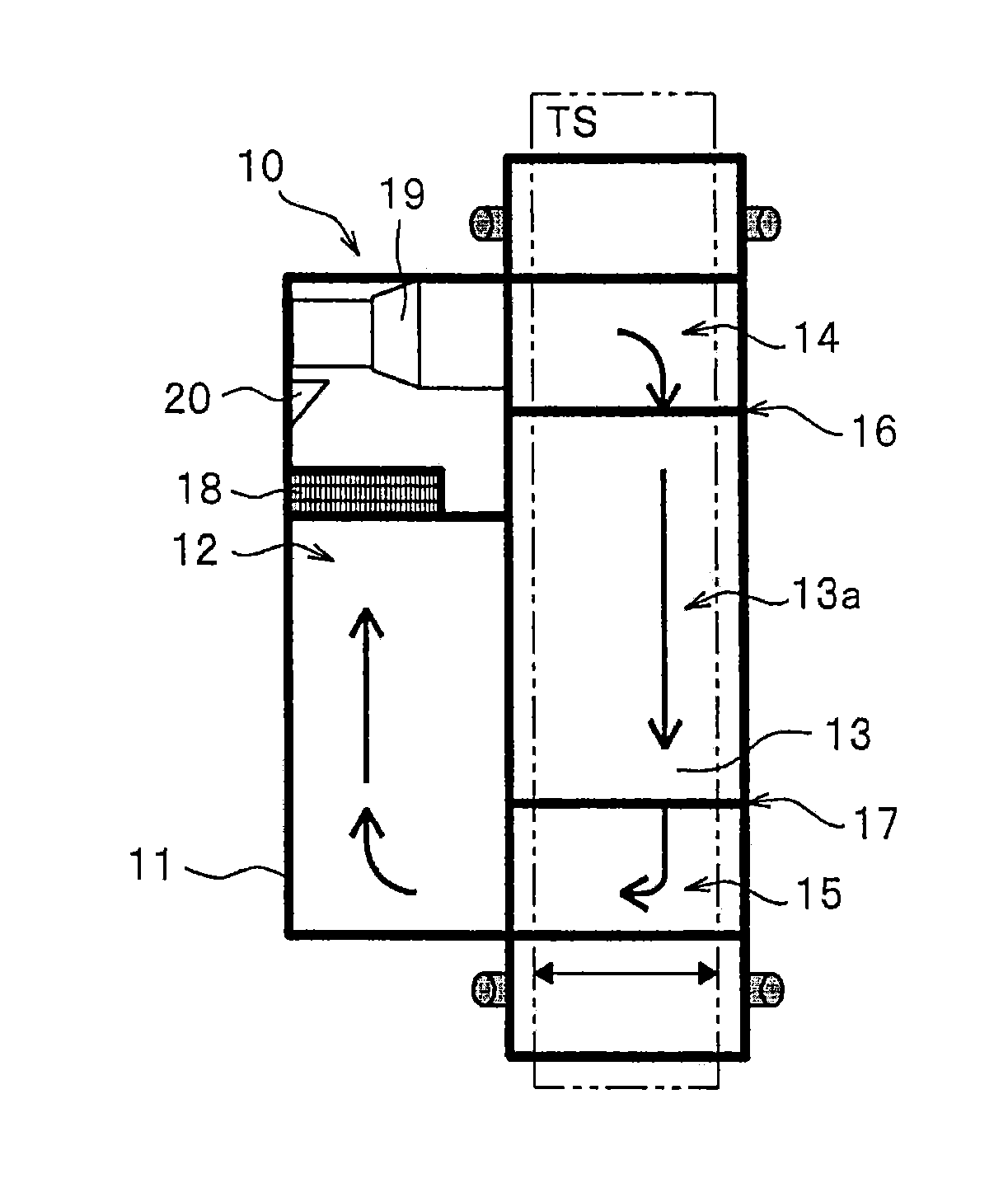
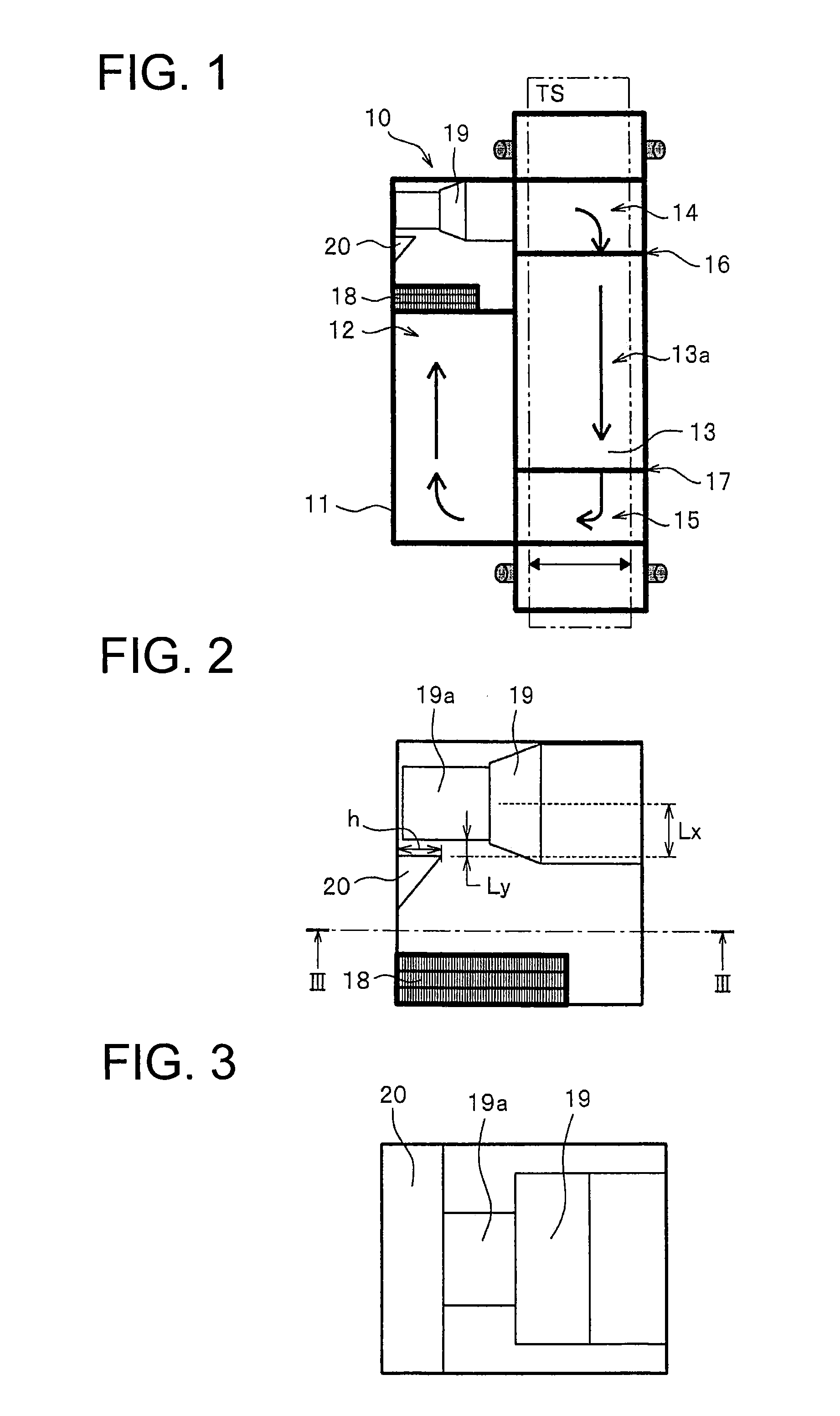
[0101]For a case in which the wind direction changing plate is installed to the heating furnace equipped with the configuration illustrated in FIG. 1 to FIG. 3 and a case in which the wind direction changing plate is not installed thereto, the path width direction temperature at the longitudinal direction central portion of each running path in the heat treatment chamber were measured at five points for each path using 4 paths formed between the upper and lower folding rollers (not illustrated) without passing the fiber sheet through the fiber sheet running paths (path) from the first stage to the fourth stage from the top, and the temperature distribution in the path width direction and height direction was examined. The average temperature in the heat treatment furnace at this time was 240° C. Incidentally, the wind direction changing plate is arranged in contact with the entire side wall surface facing the heat treatment chamber on the upstream side of the circulation fan as the ...

example 2

[0104]The experiment was conducted under the same conditions as in Example 1 except that an acrylonitrile-based precursor fiber sheet passed through the circulating flow path in the heat treatment furnace configured by the paths having the first stage to the fourth stage. The results are presented in Table 2. The temperature difference in the width direction of each path in the furnace at 240° C. on the average was 1.98° C., 2.84° C., 6.63° C., and 7.88° C. from the top as presented in Table 2.

example 3

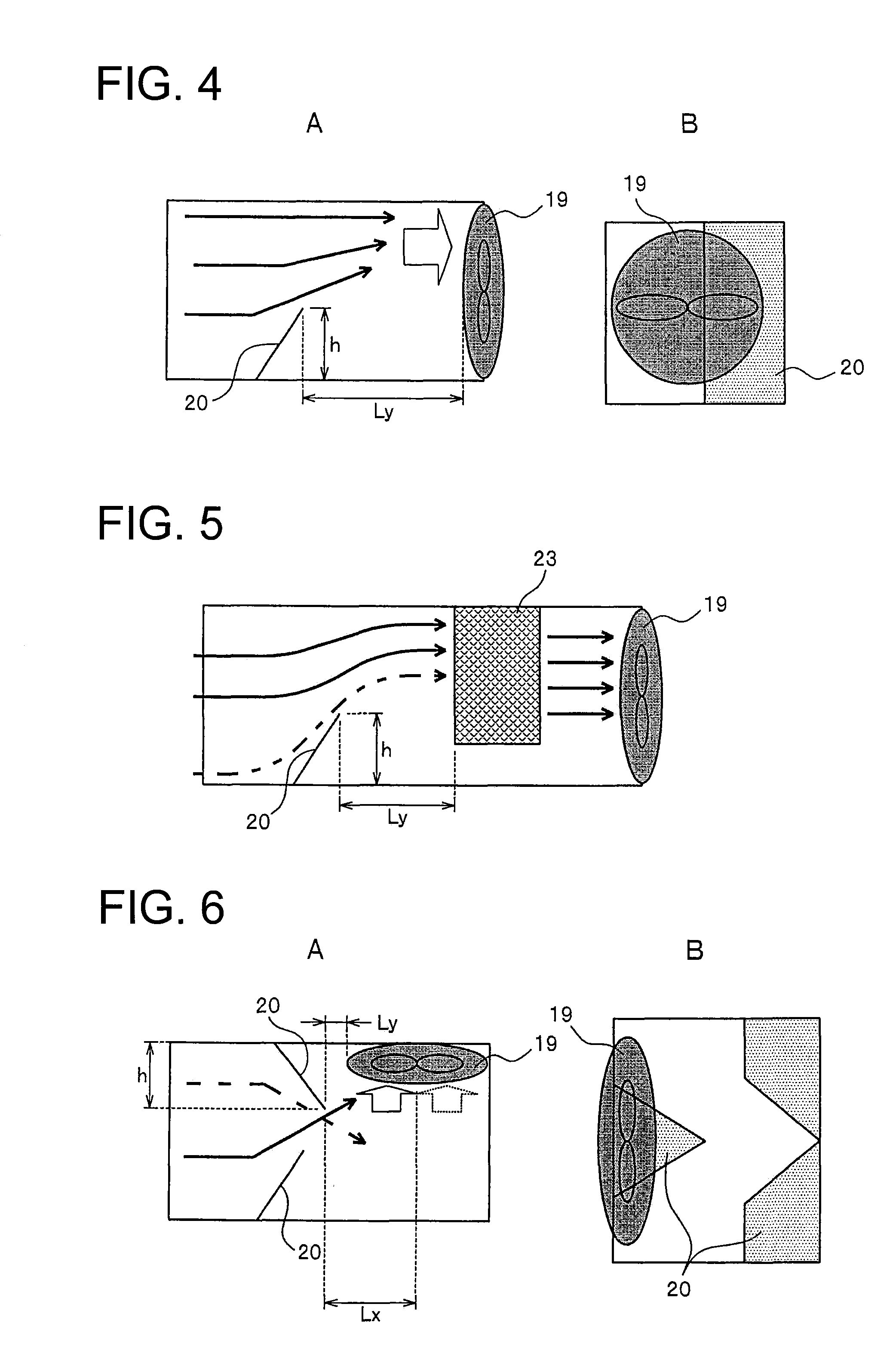
[0107]Wind direction changing plates were installed alternately in the height direction on both side surfaces as illustrated in FIG. 6 at the upstream site of the circulation fan in the flow path in which hot wind was flowing in the hot wind introduction duct having the flow path cross section of 1 m2 at an average wind velocity of 8 m / s. The average temperature in the hot wind introduction duct at this time was 236° C. Here, the circulation fan that is the hot wind mixing member is disposed to be perpendicular to the flow path direction of the hot wind introduction duct, the distance Lx from the most downstream point of the wind direction changing plate to the most upstream point of the circulation fan, which is in the parallel direction to the hot wind introduction duct is 500 mm. The length in the flow path width direction of the plate on one side is 500 mm and the length on the other side is 400 mm, and the area of all the wind direction changing plates projected on the flow pat...


PUM

PropertyMeasurementUnit
Temperatureaaaaaaaaaa
Fractionaaaaaaaaaa

Abstract

The present invention relates to a heating furnace suitable for a step in which a precursor fiber bundle is flameproofed. The heating furnace is provided with a hot air introduction duct disposed in a horizontal space and a heat treating chamber, and in the hot air introduction duct outside the heat treatment chamber, a heating device and a circulation fan for the hot air. The interior of the heat treatment chamber comprises a fiber travel path in which the fiber bundles each having a sheet shape horizontally travels the hot air flowing in a low-temperature region is directed to the high-temperature region side by an air direction change plate to be narrowed and flow in the width direction of the hot air introduction duct As a result, the temperature distribution in the width direction in the treatment chamber can be improved.

Description

TECHNICAL FIELD[0001]The present invention relates to a method for producing a carbon fiber bundle and a heating furnace of a carbon fiber precursor fiber bundle, and it particularly relates to a method for producing a carbon fiber bundle using a heating furnace of a fiber bundle that can be suitably applied to a flameproofing furnace of a precursor fiber bundle in a carbon fiber bundle production process.BACKGROUND ART[0002]The application fields of carbon fiber have been expanded more and more since it is excellent in specific strength, specific modulus, fire resistance, heat resistance, and durability. A carbon fiber is produced by firing a precursor fiber, and a process thereof includes a flameproofing process, a preliminary carbonization process, and a carbonization process. In the flameproofing process, the heat treatment of precursor fiber is performed in an oxidizing atmosphere so that the thermal stability is imparted to the precursor fiber. This flameproofing process is a ...

Claims


Application Information

Patent Timeline
IPC IPC(8): F27D7/06D01F9/12F27D7/04
CPCF27D7/06F27D7/04F27D2007/063F27D2007/045D01F9/12D01F9/32D01D10/02F26B13/001
Inventor ARAI, RISAKAJI, SATOSHIKAWAMURA, ATSUSHINISHI, HIROYUKITANAKA, TAKAFUMISHIMAHARA, MASASHI
Owner MITSUBISHI CHEM CORP
Learn More