Roundness measuring apparatus

a technology of roundness and measuring apparatus, applied in the direction of measurement devices, instruments, error compensation/elimination, etc., can solve the problems of large installation space and large temperature change, and achieve the effect of small spa

Active Publication Date: 2016-06-09
TOKYO SEIMITSU
View PDF12 Cites 16 Cited by
  • Summary
  • Abstract
  • Description
  • Claims
  • Application Information

AI Technical Summary

Benefits of technology

[0023]According to the present invention, a roundness measuring apparatus with a small space required for installation is realized.

Problems solved by technology

For the above reasons, the conventional roundness measuring apparatuses need the setting space of a rectangle shape being long in the radial direction, and there has been a problem that a space required for installation is large.
Since a conventional roundness measuring apparatus has a long arm 6, there has been a problem that a displacement of the detector 10 attached at the tip of the arm 6 and the detector holder 9 is large even if there is a small temperature change in a short time during measurement.
Further, since the displacement directly influences a measurement value, there has been a problem that an error due to the temperature change is large.

Method used


Image

  • Roundness measuring apparatus
  • Roundness measuring apparatus
  • Roundness measuring apparatus

Examples


first embodiment

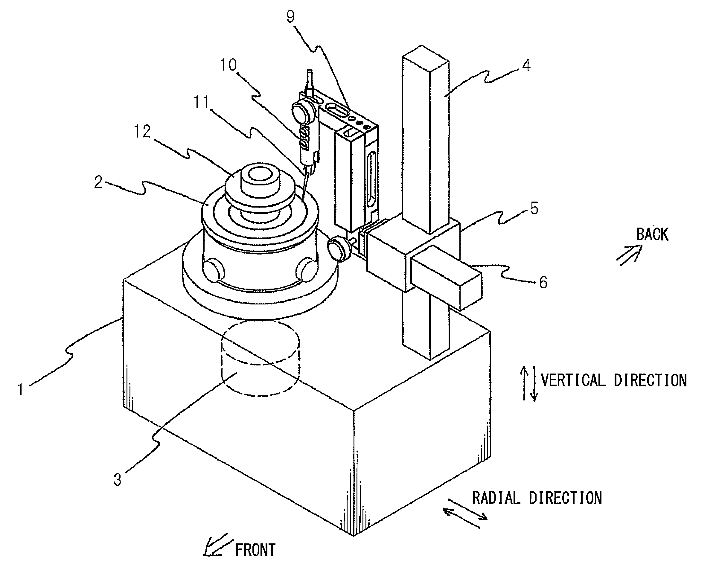
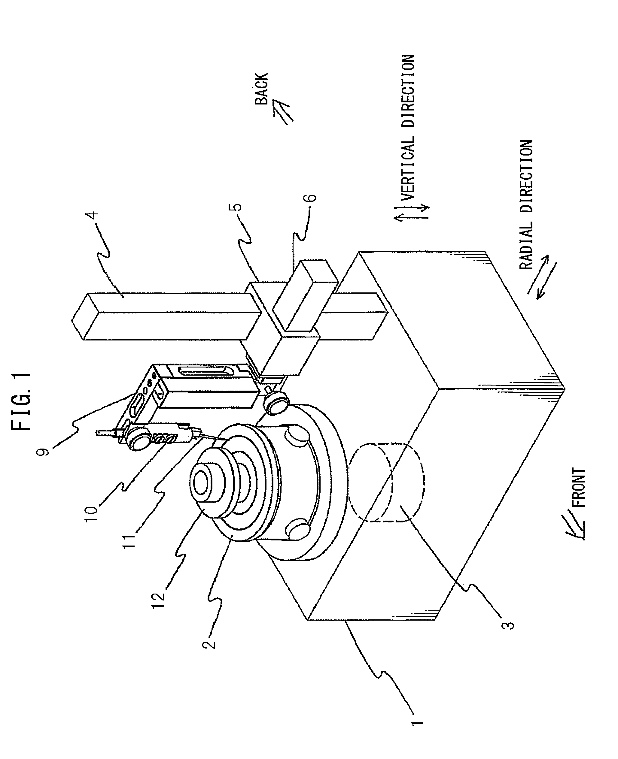
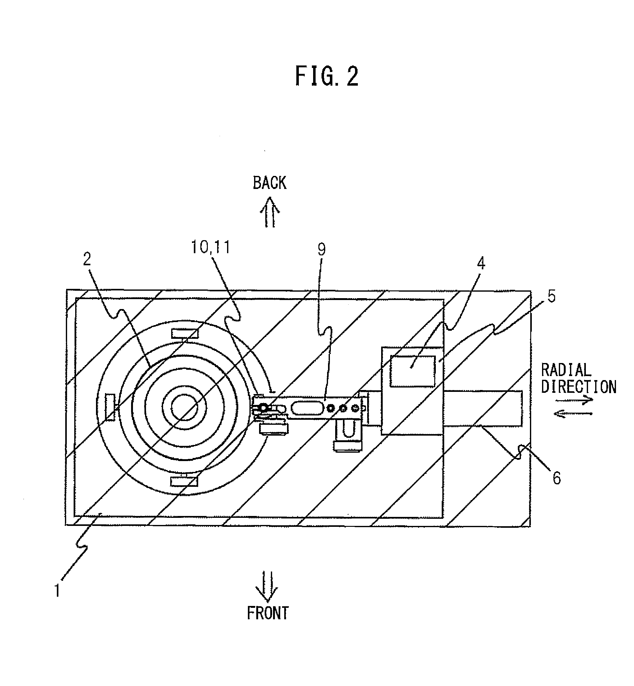
[0034]FIG. 3 and FIG. 4 are outline views seen from a front side and a back side of a roundness measuring apparatus of the present invention.

[0035]The roundness measuring apparatus of the first embodiment includes: a table-like base 21; a rotatable stage 22 provided at the base 21; a rotation drive part (not shown) having a motor for rotating the stage 2, etc.; a column 24 provided at the back of the base 21; a carriage 25 which is movable along the column 24; a detector holder 29 attached to the carriage 25; and a detector 30 attached to the detector holder 29. The detector 30 has a probe 31 and displacement detection parts, such as a differential transformer, and outputs an electrical signal which shows displacement of the probe 31. The carriage 25 is also called a holder holding part since the detector holder 29 is attached to the carriage 25.

[0036]Vertical direction guides 51 and 52 and a vertical direction feed screw 53 are provided on the column 24. The carriage 25 is engaged ...

second embodiment

[0050]FIG. 8 and FIG. 9 are outline views seen from a front side and a back side of a roundness measuring apparatus of the present invention.

[0051]The roundness measuring apparatus of the second embodiment is different from the roundness measuring apparatus of the first embodiment in that two groups of columns, carriages, detector holders and detectors are provided.

[0052]As illustrated in the figures, the roundness measuring apparatus of the second embodiment includes: a table-like base 21; a rotatable stage 22; a rotation drive part (not shown); two columns 24A and 24B; two carriages 25A and 25B; two detector holders 29A and 29B; and two detectors 30A and 30B.

[0053]On the column 24A, vertical direction guides 51A and 52A and a vertical direction feed screw 53A are provided. The carriage 25A is engaged with the vertical direction feed screw 53A by a vertical direction feed nut. By rotating a vertical direction feed knob 55A, the vertical direction feed screw 53A rotates and the carr...

third embodiment

[0056]FIG. 10 is an outline view of a roundness measuring apparatus of the present invention.

[0057]The roundness measuring apparatus of the third embodiment differs from the roundness measuring apparatus of the first embodiment in that the column 24 is fixed and the detector holder moving mechanism 81, which moves the detector holder 29 in parallel to the measurement plane, is provided at the carriage 25.

[0058]In FIG. 10, although the illustration of the moving mechanism of the carriage 25 provided on the column 24 is omitted, the moving mechanism similar to that used in the first embodiment is used.

[0059]The detector holder moving mechanism 81 is fixed to the carriage 25, and the detector holder moving mechanism 81 is realized by a moving mechanism, which includes a pair of guides, a feed screw and a feed nut, similar to that of the first embodiment. However, the illustration of the detector holder moving mechanism 81 is omitted in FIG. 10. The detector holder moving mechanism 81 m...


PUM


Abstract

A roundness measuring apparatus, which has a small space required for installation and of which measurement error due to a temperature change is small, is disclosed. The roundness measuring apparatus includes: a base; a turn-table which is fixed to the base and rotates a work placed on the turn-table; a two-dimensional moving mechanism provided at the base so as to move a holder holding part in parallel to a measurement plane including a rotation axis of the turn-table and a measuring point of the work; a detector holder attached to the holder holding part; and a detector attached to the detector holder so that a probe can be displaced on the measurement plane.

Description

TECHNICAL FIELD[0001]The present invention relates to a roundness measuring apparatus.BACKGROUND TECHNOLOGY[0002]The roundness measuring apparatus which measures a roundness of a cylinder outer surface or a cylinder inner surface of an object (work) to be measured is used widely.[0003]FIG. 1 is an outline view of a conventional roundness measuring apparatus.[0004]The roundness measuring apparatus includes: a table-like base 1; a rotatable stage 2 provided at the base 1; a rotation drive part 3 having a motor, etc., for rotating the stage 2; a column 4 provided at the base 1; a carriage 5 which is movable along the column 4; an arm 6 which is movable with respect to the carriage 5; a detector holder 9 attached to a tip of the arm 6; and a detector 10 attached to the detector holder 9. The detector 10 includes a probe 11 and a displacement detection part such as a differential transformer, and outputs an electrical signal which shows displacement of the probe 11.[0005]A work 12 is pla...

Claims


Application Information

Patent Timeline
Patent Type & Authority Applications(United States)
IPC IPC(8): G01B5/20
CPCG01B5/201G01B5/0014G01B5/20
Inventor TAKANASHI, RYO
Owner TOKYO SEIMITSU
Why Eureka
Try Eureka