Backlight Assembly with Lightproof Arrangement

Inactive Publication Date: 2016-06-09
SUN SZU WEI
View PDF2 Cites 2 Cited by
  • Summary
  • Abstract
  • Description
  • Claims
  • Application Information

AI Technical Summary

Benefits of technology

[0006]It is therefore one object of the invention to provide a backlight assembly comprising upper and lower reflective layers secured together and folded to form a concealed space; a light guide layer disposed in the space and including at least one light entrance; an opaque blocking layer disposed at either side por

Problems solved by technology

However, light may be leaked as it passes through multi-structure consisting of the light guide layer, the reflector plate, the light shading plate and the circuit board.
As such, in

Method used


Image

  • Backlight Assembly with Lightproof Arrangement
  • Backlight Assembly with Lightproof Arrangement
  • Backlight Assembly with Lightproof Arrangement

Examples


Example

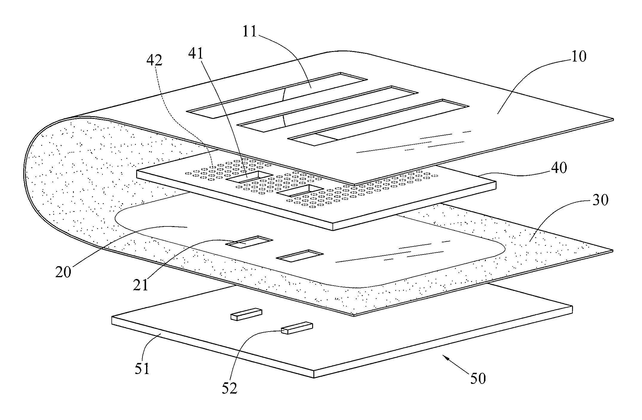
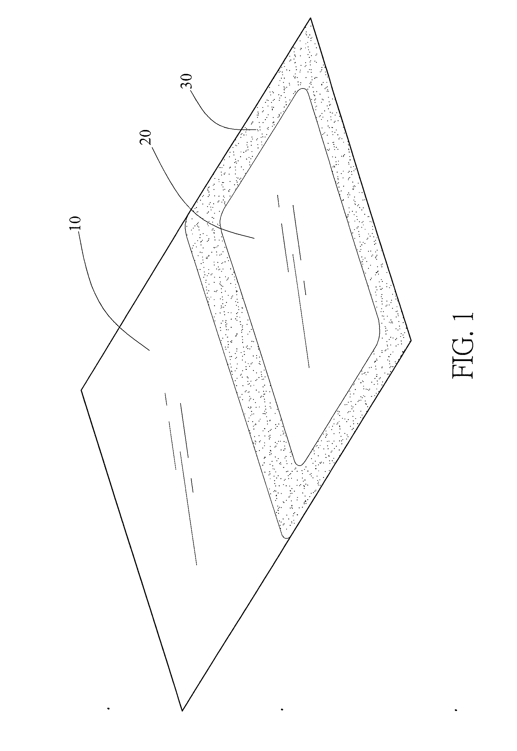
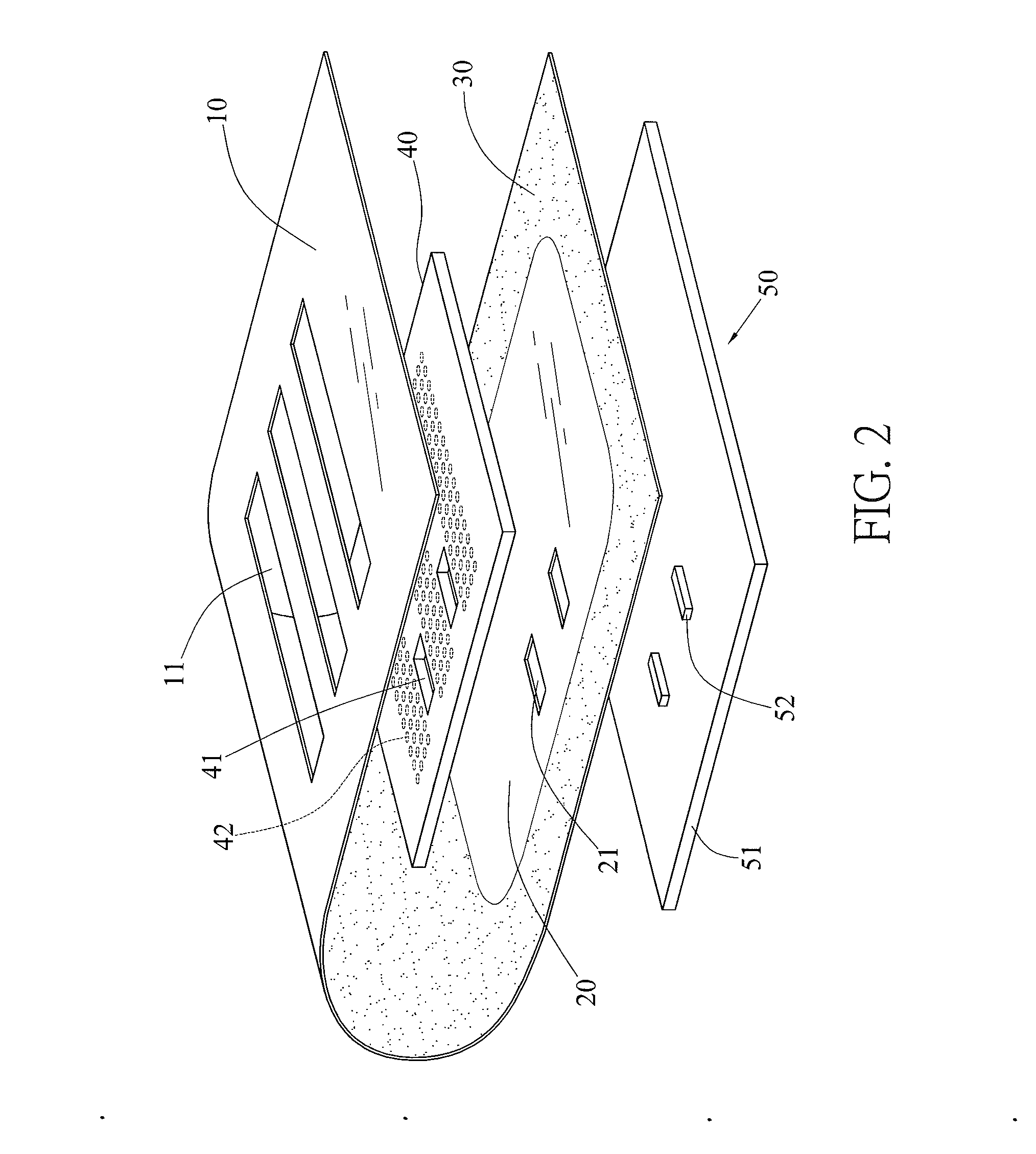
[0013]Referring to FIGS. 1 to 3, a backlight assembly in accordance with a first preferred embodiment of the invention comprises the following components as discussed in detail below.

[0014]An upper reflective layer 10 and a lower reflective layer 20 are provided. The upper and lower reflective layers 10, 20 are unitary and folded to form a concealed space 60 therebetween. The upper reflective layer 10 includes a plurality of transparent areas 11 and the lower reflective layer 20 includes a plurality of through holes 21. A light guide layer 40 is provided in the space 60. An opaque blocking layer 30 is provided at either portion joining the upper and lower reflective layers 10, 20. The opaque blocking layer 30 is adjacent to the light guide layer 40. The light guide layer 40 includes a plurality of through holes 41 directly above the through holes 21, and a plurality of reflective areas 42, on the underside, the reflective areas 42 being beneath the transparent areas 11. A light sour...


PUM


Abstract

A backlight assembly is provided with upper and lower reflective layers secured together and folded to form a concealed space; a light guide layer in the space and including at least one light entrance; an opaque blocking layer at either side portion joining the upper and lower reflective layers; and at least one light source each at the light entrance. Light emitted by the light source travels to the light entrance, and further travels to predetermined areas via paths defined by the upper and lower reflective layers. Light leaking is decreased to a minimum during light transmitting.

Description

BACKGROUND OF THE INVENTION[0001]1. Field of the Invention[0002]The invention relates to backlight assembly and more particularly to a backlight assembly having a lightproof arrangement so that light with enhanced brightness is transmitted to predetermined positions (i.e., bottoms of keycaps of a keyboard or keypad) of a 3C (computer, communication, and consumer electronics) product with light leaking decreased to a minimum during light transmitting.[0003]2. Description of Related Art[0004]Backlight is widely used in many electronic products and lights such as keyboards, keypads, notebook computers, mobile phones, and displays. A conventional backlight assembly is comprised of a light guide layer, a reflector plate, a light shading plate and circuit board. The plates are manufactured separately prior to stacking in the manufacturing process. However, light may be leaked as it passes through multi-structure consisting of the light guide layer, the reflector plate, the light shading p...

Claims


Application Information

Patent Timeline
IPC IPC(8): F21V8/00
CPCG02B6/0088G02B6/0031G02B6/0055G02B6/0073G02B6/0021G02B6/006H01H13/83H01H2219/06H01H2219/062H01H2219/064
Inventor SUN, SZU-WEI
Owner SUN SZU WEI
Why Eureka
Try Eureka