
An Electrical Hair Removal Device and Control Method

a hair removal device and control method technology, applied in the field of electrical hair removal devices and control methods of electrical removal devices, can solve the problems of different stubbles, pain, and inability to close shave, and achieve the effects of reducing pain, and reducing the heating temperature grad

Inactive Publication Date: 2016-06-16
405 LIMITED COMPANY SHENZHEN
View PDF3 Cites 13 Cited by
  • Summary
  • Abstract
  • Description
  • Claims
  • Application Information

AI Technical Summary

Benefits of technology

The present invention is an electrical hair removal device that includes a heat generator and a cutting element for removing hair on the skin. The device allows for an instant start upon use mode, is very safe and convenient, and provides multiple grades heating temperature ranges for users to choose from. The heating wire is not directly contact with the skin, preventing high temperatures from burning the skin. The device also utilizes a removable heat generator for easy repair or replacement. The cooperation of the heat generator and cutting element can completely remove the hair on the skin, no matter the longer or shorter hair. The device provides different work modes for different user needs.

Problems solved by technology

In use, the shave razor is uncomfortable to use, takes pain, and can't get a close shave, and results in different stubbles remaining thereon.
Especially, the shave razor is easy to damage skin, which not only doesn't realize the beauty, but also leaves disfigurement security risk.
The electrolysis device has a low efficiency and high security risk.
However, a conventional heating wire for shaving hair utilizes high temperature heat, which usually damages the skin.
In addition, there's still other questions, such as some hot-curled stubble remaining on the skin after an heat removal process.
It is so inconvenient.
At the same time, the heating wire can't be designed to be very closer to the skin, for preventing scalding the skin.
So, there's some very shorter hair can't be removed , which looks so ugly, and touches so ruffly.

Method used


Image

  • An Electrical Hair Removal Device and Control Method
  • An Electrical Hair Removal Device and Control Method
  • An Electrical Hair Removal Device and Control Method

Examples


Embodiment Construction

[0064]Reference will now be made to the drawings to describe preferred and exemplary embodiments in details.

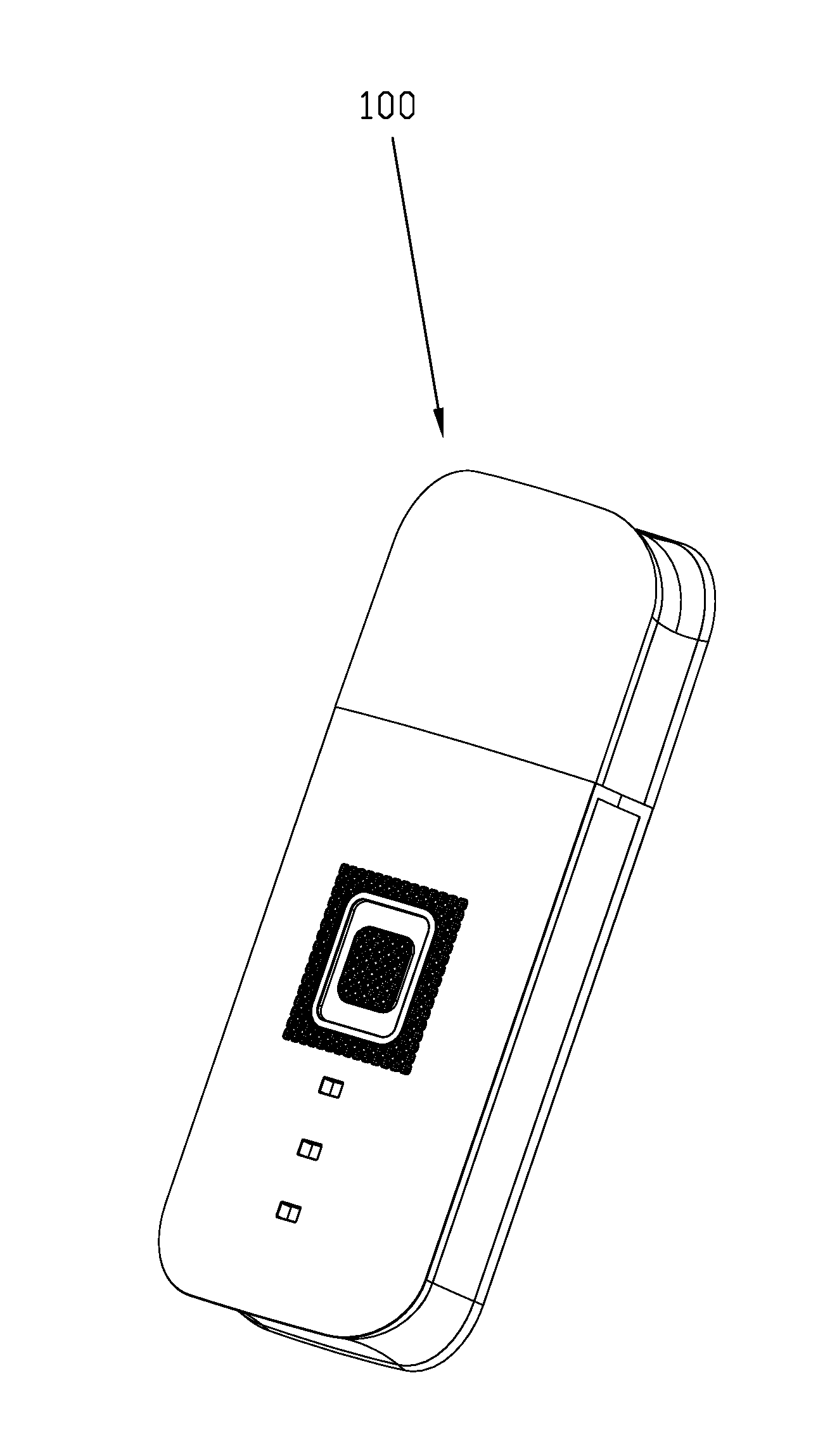
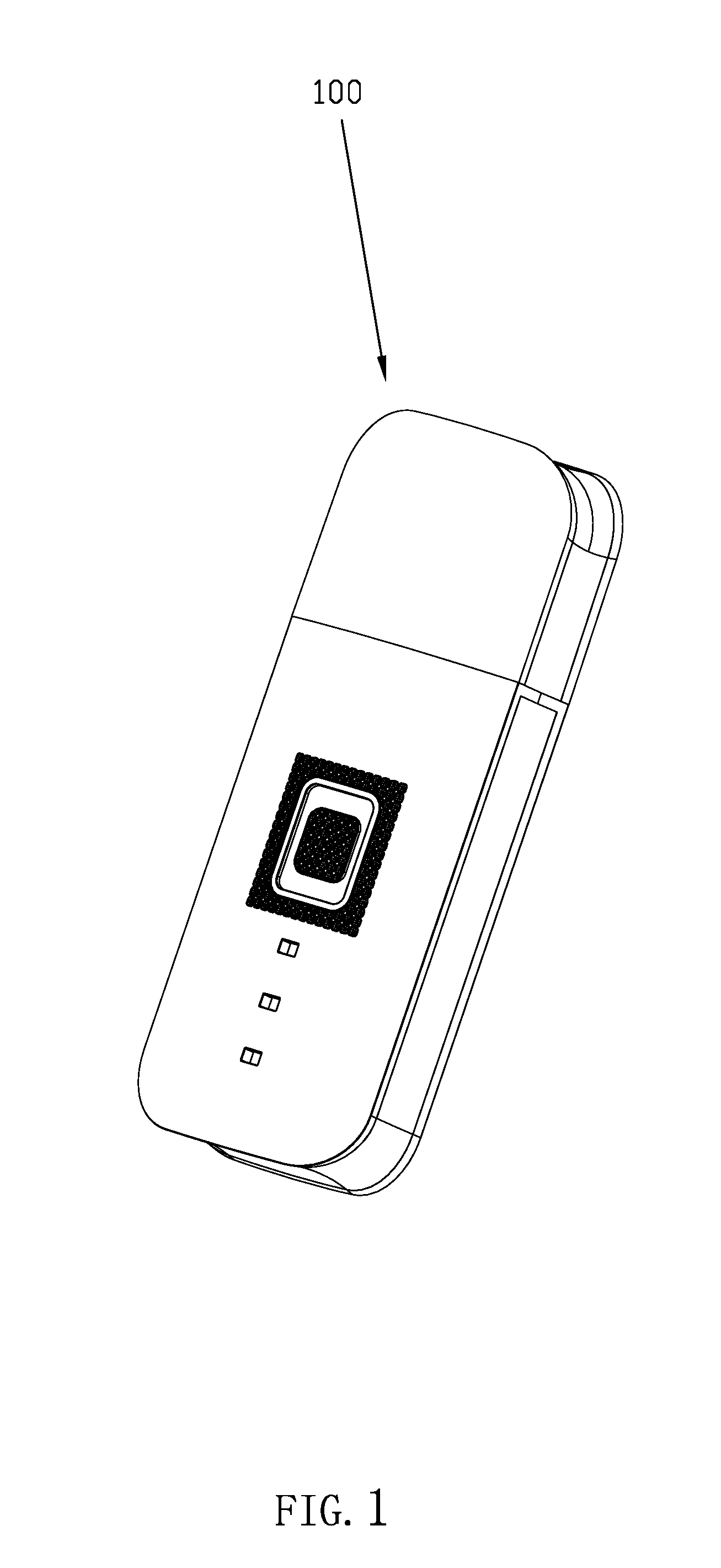
[0065]Referring to FIG. 1, an electrical hair removal device according to a first embodiment of the invention is shown. The electrical hair removal device 100 is shaped like a rectangular, having four arc-shaped transition designs at four corners, respectively. The electrical hair removal device 100 has a length greater than its width and thickness, the length being 2-5 times the width, and being 3-10 times the thickness, which assures an easier holding for a user. For maintaining an ergonomic design, the length of the electrical hair removal device 100 is almost similar to that of a human hand, the width is less than that of any part of a human body, and the thickness is designed to be as thinner as possible. Thus, the electrical hair removal device 100 has a compact structure, facilitates the use, and assures a human oriented design.

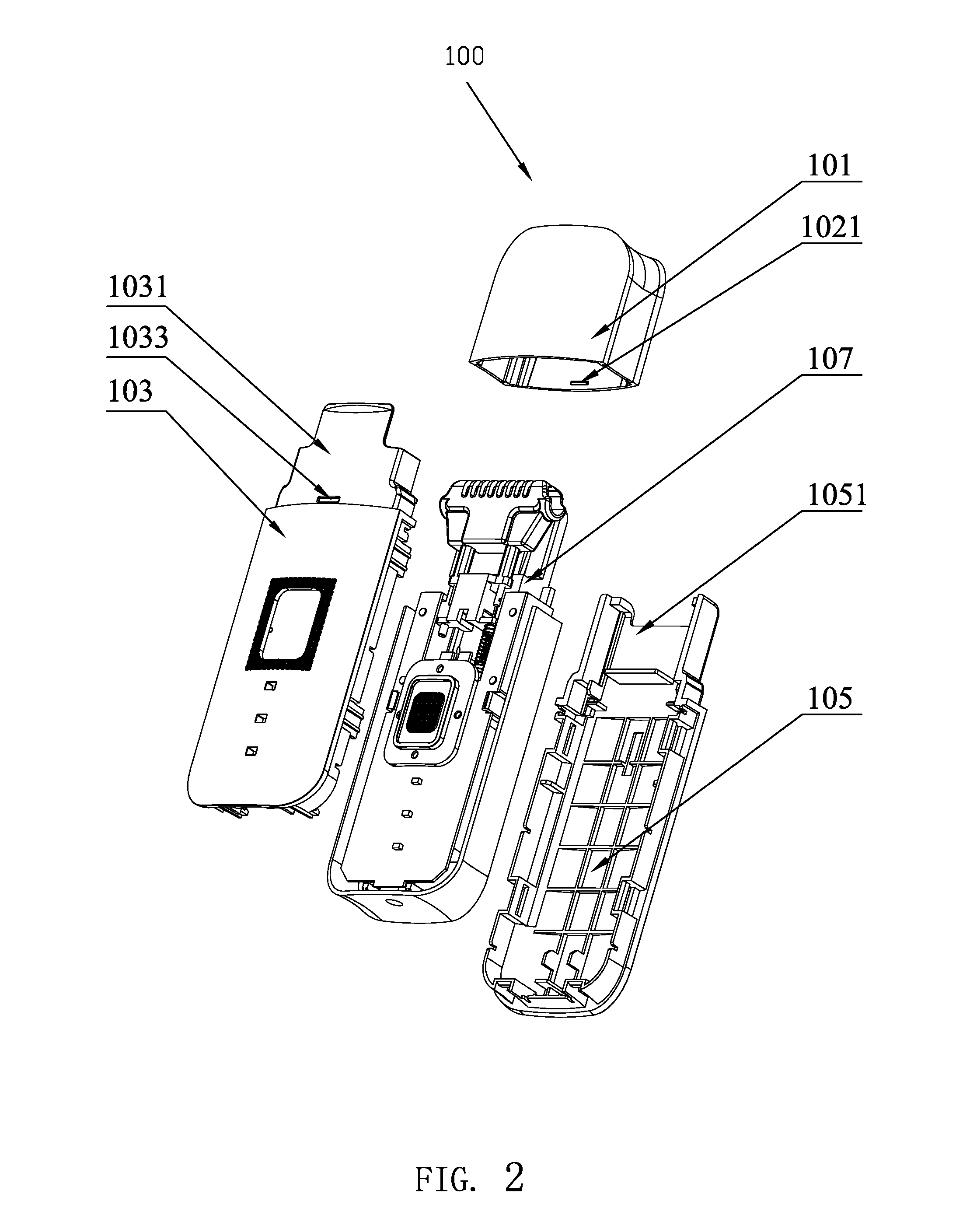
[0066]Referring to FIG. 2, the electrical ...


PUM


Abstract

A control method for an electrical hair removal device, the electrical hair removal device including a heat generator having a heating wire formed thereon, including the steps of step S11: starting the electrical hair removal device and letting it go into a standby state; step S12: placing the heat generator on an hair removal needed area; and step S13: electrifying the heating wire to a predetermined temperature, for realizing hair removal with a constant heating temperature. An electrical hair removal device includes a main body and a cover for accommodating the main body. The main body has a heat generator having a heating wire thereon, a supporting element and a printed circuit board (PCB). The heating wire is electrically connected to the PCB, which is electrified and heated to a predetermined temperature, for realizing hair removal with a constant heating temperature.

Description

RELATED APPLICATIONS[0001]This application is a PCT National Stage of PCT Patent Application No. PCT / CN2014 / 081698, filed Jul. 4, 2014, and claims benefit to Chinese Patent Application No. CN201310279972.4, filed Jul. 4, 2013, and Chinese Patent Application No. CN201410312038.2, filed Jul. 1, 2014.[0002]The above applications and all patents, patent applications, articles, books, specifications, other publications, documents, and things referenced herein are hereby incorporated herein in their entirety for all purposes. To the extent of any inconsistency or conflict in the definition or use of a term between any of the incorporated publications, documents, or things and the text of the present document, the definition or use of the term in the present document shall prevail.BACKGROUND OF THE INVENTION[0003]1. Field of Invention[0004]The present invention relates to an electrical removal device and a control method for the electrical removal device, and more particularly to an electr...

Claims


Application Information

Patent Timeline
Patent Type & Authority Applications(United States)
IPC IPC(8): A45D26/00H05B3/06H05B3/00
CPCA45D26/0009H05B3/06H05B3/00A45D26/00A61B18/082A61B2018/00476A45D26/0004
Inventor OGUCHI, YOKO
Owner 405 LIMITED COMPANY SHENZHEN
Learn More