Eureka AIR delivers breakthrough ideas for toughest innovation challenges, trusted by R&D personnel around the world.

Bicycle saddle

a saddle and bicycle technology, applied in the field of saddles, can solve the problems of reducing blood flow and possible nerve damage for both men and women, unable to achieve any significant degree of market success, and threw the torso of the rider in a forward direction, so as to prevent the forward displacement of the seat bones and maintain the balance of the rider's hips

Inactive Publication Date: 2016-06-16
DUDLEY II JACKSON C
View PDF22 Cites 6 Cited by
  • Summary
  • Abstract
  • Description
  • Claims
  • Application Information

AI Technical Summary

Benefits of technology

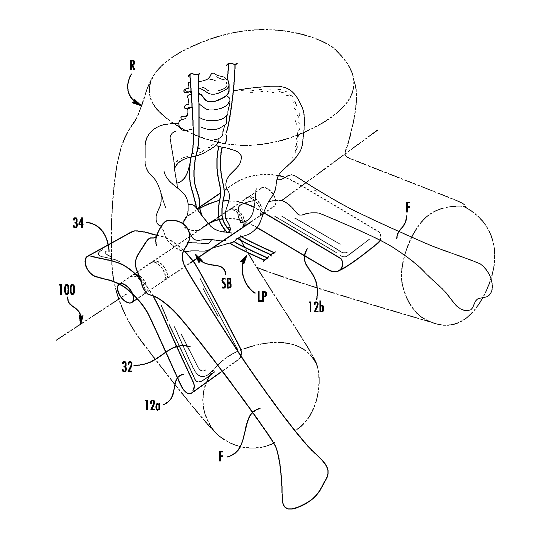
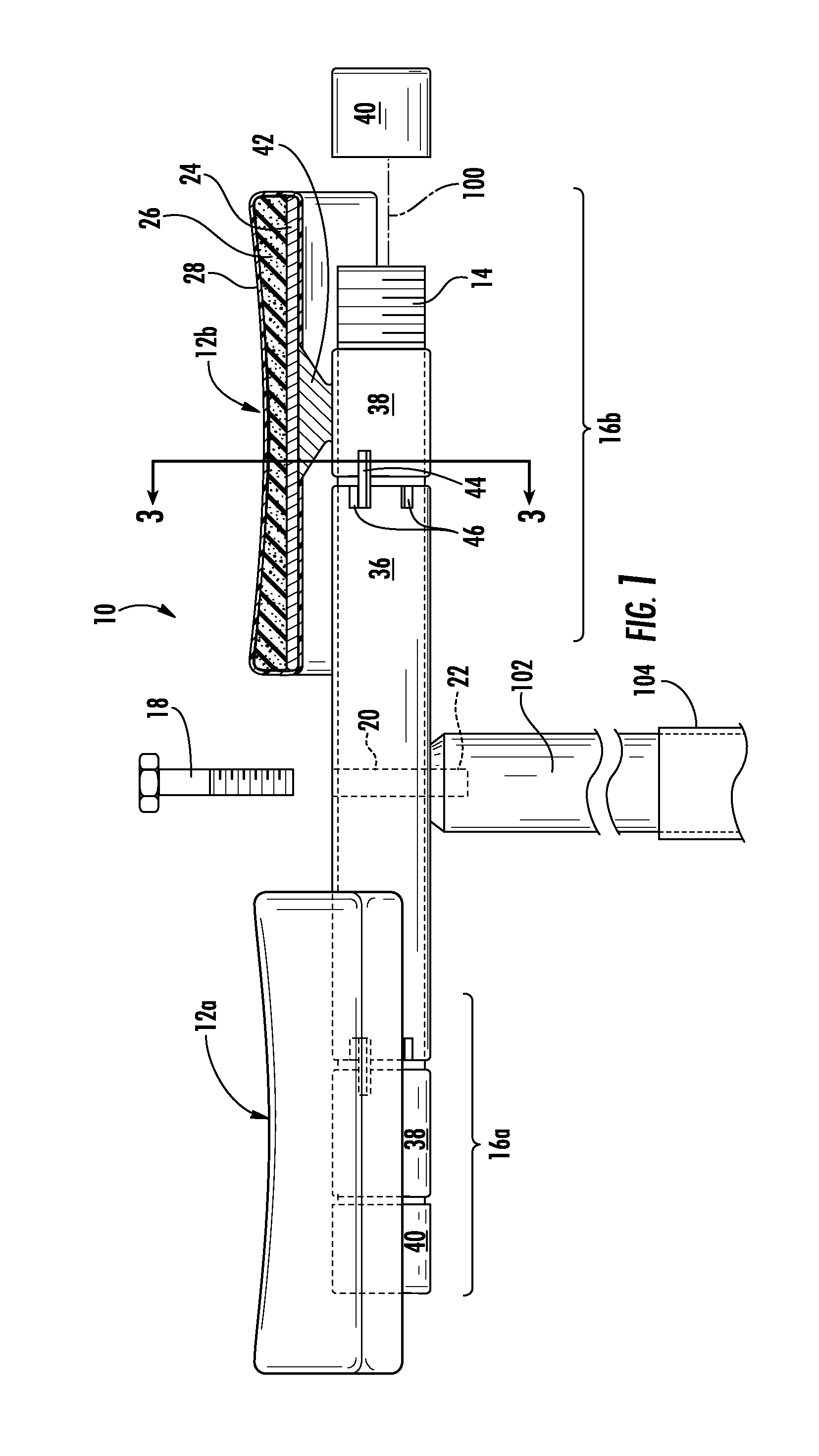
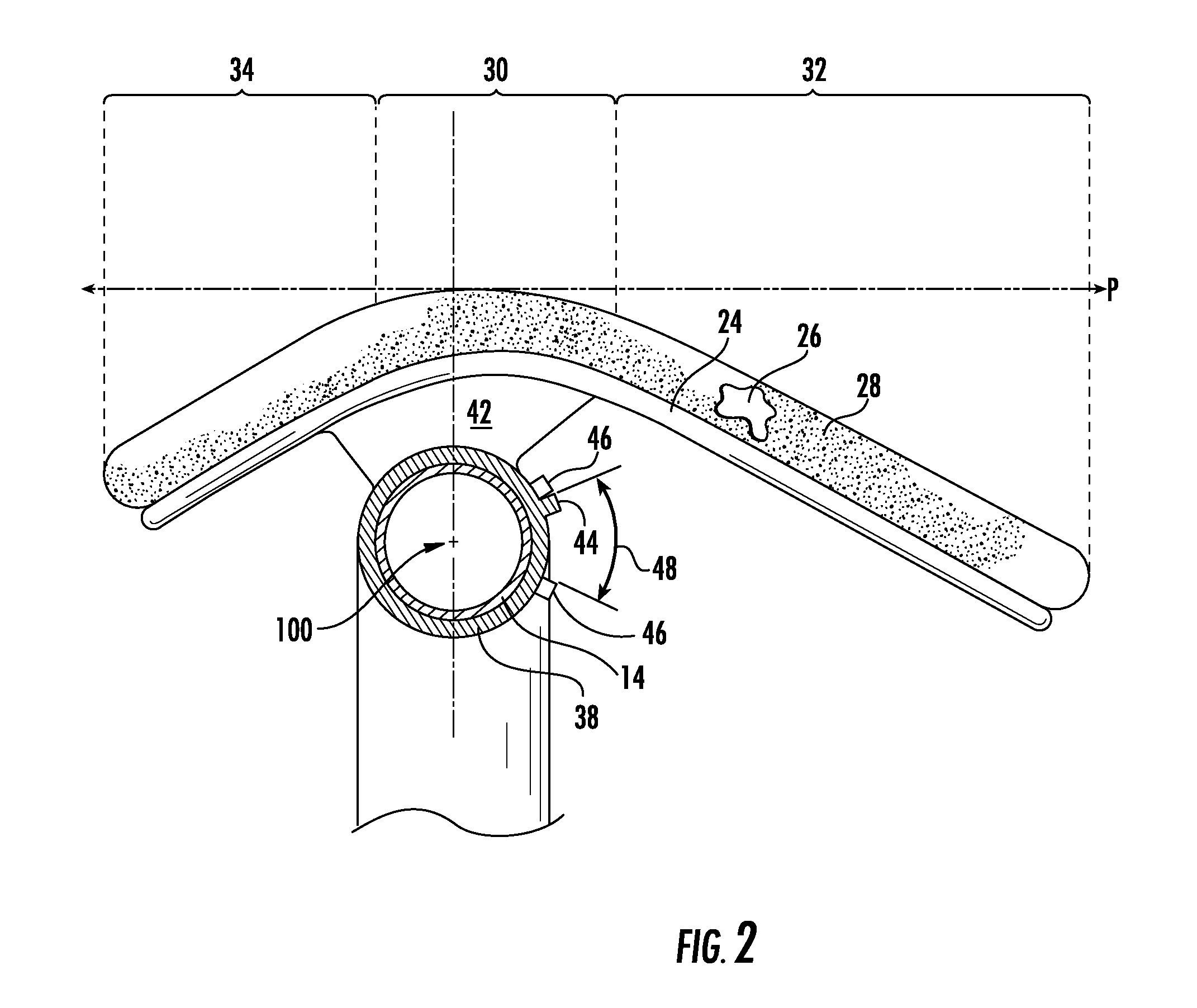
The present invention is a new kind of saddle for bicycles, tricycles, and other peddle-operated devices. The saddle has a pair of rider supports that pivot on an axel, allowing the rider to move their legs freely during pedaling. The rider supports are designed to match the contour of the rider's buttocks and thighs, providing a more comfortable ride. The saddle is also designed to prevent pain and discomfort caused by conventional bicycle saddles, maintaining the rider's proper riding position and allowing them to bear weight on the large surfaces of their lower buttocks and upper legs. The saddle is also easy to assemble and low-cost.

Problems solved by technology

Although riding an upright bicycle is a common form of exercise employed not only for enjoyment but for improving the cardiovascular system, cycling often imparts prolonged pressure on the rider's sub-perineum, more commonly referred to as the crotch area, resulting in reduced blood flow and possible nerve damage for both men and women.
While the Barker split seat attempted to obviate the above-mentioned side effects associated with conventional bicycle seats, it failed to achieve any significant degree of market success.
This may be due in part to what may be considered a design flaw, namely that the shape and orientation of each rider support relative to its axis of rotation are such that, when pivoted during the peddling cycle, they cause the rider's hips to be thrown off their horizontal axis and further throw the rider's torso in a forward direction off of the support.

Method used


Image

  • Bicycle saddle
  • Bicycle saddle
  • Bicycle saddle

Examples


Embodiment Construction

[0025]It should be clearly understood at the outset like reference numerals are intended to identify the same structural elements, portions or surfaces consistently throughout the several drawings herein, as such elements, portions or surfaces may be further described or explained by the entire written specification, of which this detailed description is an integral part. Unless otherwise indicated, the drawings are intended to be read (e.g., cross-hatching, arrangement of parts, proportion, degree, etc.) together with the specification, and are to be considered a portion of the entire written description of this invention. As used in the following description, any reference to the terms “horizontal”, “vertical”, “left”, “right”, “up” and “down”, as well as adjectival and adverbial derivatives thereof (e.g., “horizontally”, “rightwardly”, “upwardly”, etc.), simply refer to the orientation of the illustrated structure as the particular drawing figure faces the reader. Similarly, the ...


PUM


Abstract

A saddle for peddle operated devices such as bicycles, tricycles, stationary bikes comprises a pair of rider supports sized to support the regions of the ischium and upper femur of the rider, each rider support being pivotally mounted to a normally horizontal mounting member (i.e., an “axel”) so as to provide a limited amount of free tilting movement about a common axis of rotation thus enabling unobstructed pedaling motion of the legs. The unique curvature of the rider supports allows the rider to maintain contact with the seat during a peddling cycle (rather than being thrown forward), maintain orientation of the rider's sit bones above the rider support axis of rotation during the peddling cycle and keep the rider's hips in balance during the peddling cycle.

Description

RELATED APPLICATION[0001]This application claims the benefit of U.S. Provisional Application No. 62 / 090,007 filed Dec. 10, 2014 and entitled, Bicycle Saddle.FIELD OF THE INVENTION[0002]The present invention pertains to a rider support assemblies for pedal-operated devices such as bicycles, bicycles, stationary bikes and the like, and more particularly to those of the split seat or “noseless” variety.BACKGROUND OF THE INVENTION[0003]A bicycle saddle, often called a seat, is one of three contact points on a pedal operated device, the others being the pedals and the handlebars. Although riding an upright bicycle is a common form of exercise employed not only for enjoyment but for improving the cardiovascular system, cycling often imparts prolonged pressure on the rider's sub-perineum, more commonly referred to as the crotch area, resulting in reduced blood flow and possible nerve damage for both men and women.[0004]Heretofore, a myriad of what are referred to as “anatomically correct” ...

Claims


Application Information

Patent Timeline
IPC IPC(8): B62J1/06B62J1/00
CPCB62J1/007B62J1/06B62J1/005
Inventor DUDLEY, II, JACKSON C.
Owner DUDLEY II JACKSON C
Why Eureka
Eureka Blog
Learn More