Pulsation damper and high-pressure fuel pump

a pulsation damper and fuel pump technology, applied in the direction of liquid fuel engines, machines/engines, positive displacement liquid engines, etc., can solve the problems of reducing a pulsation damping performance, large amplitude, interior car noise, etc., to achieve sufficient pulsation damping performance, reduce vibration transmission, and reduce vibration transmission

Inactive Publication Date: 2016-06-16
TOYOTA JIDOSHA KK
View PDF10 Cites 13 Cited by
  • Summary
  • Abstract
  • Description
  • Claims
  • Application Information

AI Technical Summary

Benefits of technology

[0031]According to the above aspect, it is possible to sufficiently damp a fuel pressure pulsation on an intake side. Further, it is possible to provide a high-pressure fuel pump that is able to restrain vibration transmission to the support side while using diaphragms having different sizes together
[0032]According to the above aspect, it is possible to provide a pulsation damper and a high-pressure fuel pump each of which is able to secure a sufficient pulsation damping performance by use of a plurality of diaphragms, and to restrain vibration transmission to a support side even if diaphragms having different sizes are used together.

Problems solved by technology

This causes the diaphragm to vibrate at a large amplitude, thereby inducing vibration of a fuel pipe, its support member, and so on, which might decrease a pulsation reduction performance.
Further, when a large vibration occurring in the diaphragm is transmitted from the high-pressure fuel pump to a vehicle-body side via the fuel pipe or transmitted to an engine or the like that supports the high-pressure fuel pump, interior car noise and the like might be caused.
Further, when diaphragms having the same size are used together, two diaphragms may cause resonance frequencies at the same time, so that the resonance frequencies are combined, thereby causing a large amplitude.
This induces vibration of a fuel pipe, its support member, and so on, which might decrease a pulsation reduction performance or increase the vibration.

Method used


Image

  • Pulsation damper and high-pressure fuel pump
  • Pulsation damper and high-pressure fuel pump
  • Pulsation damper and high-pressure fuel pump

Examples


Embodiment Construction

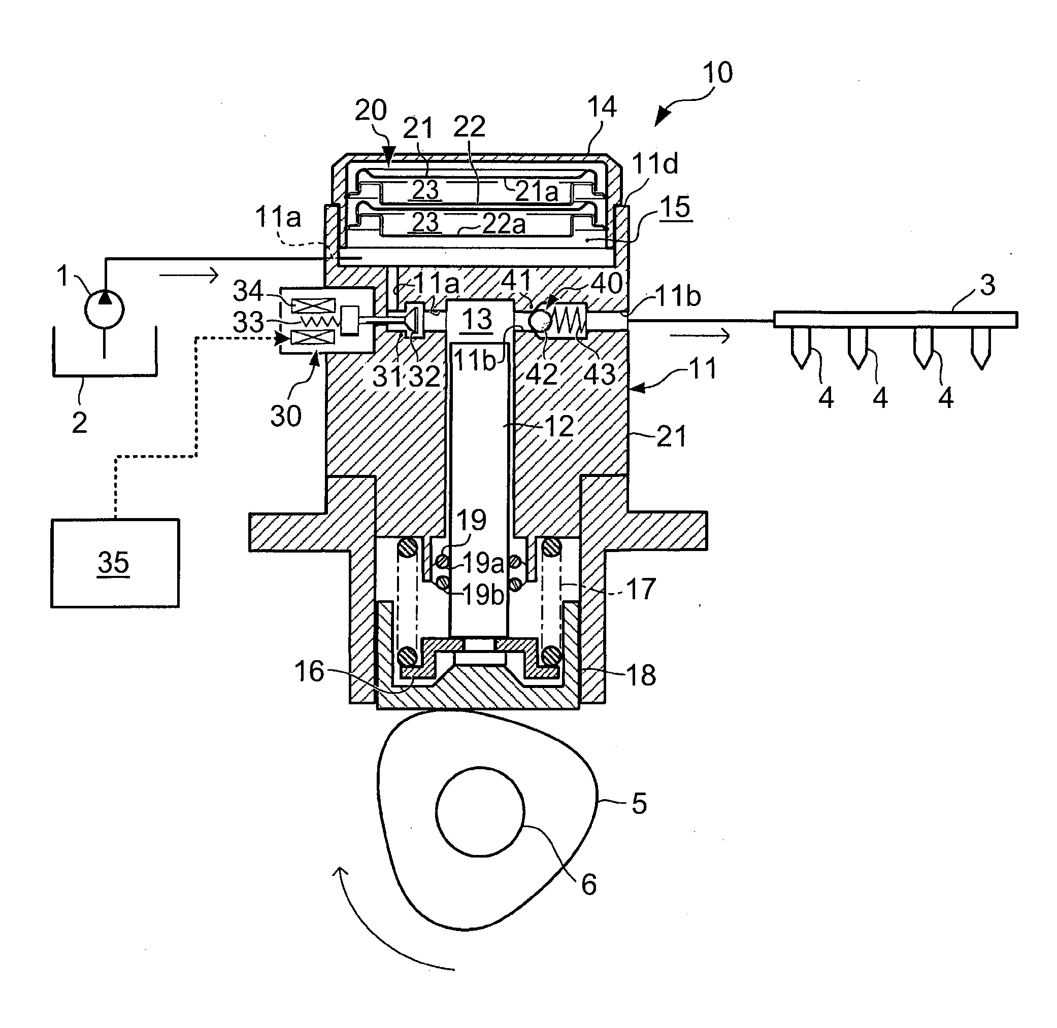
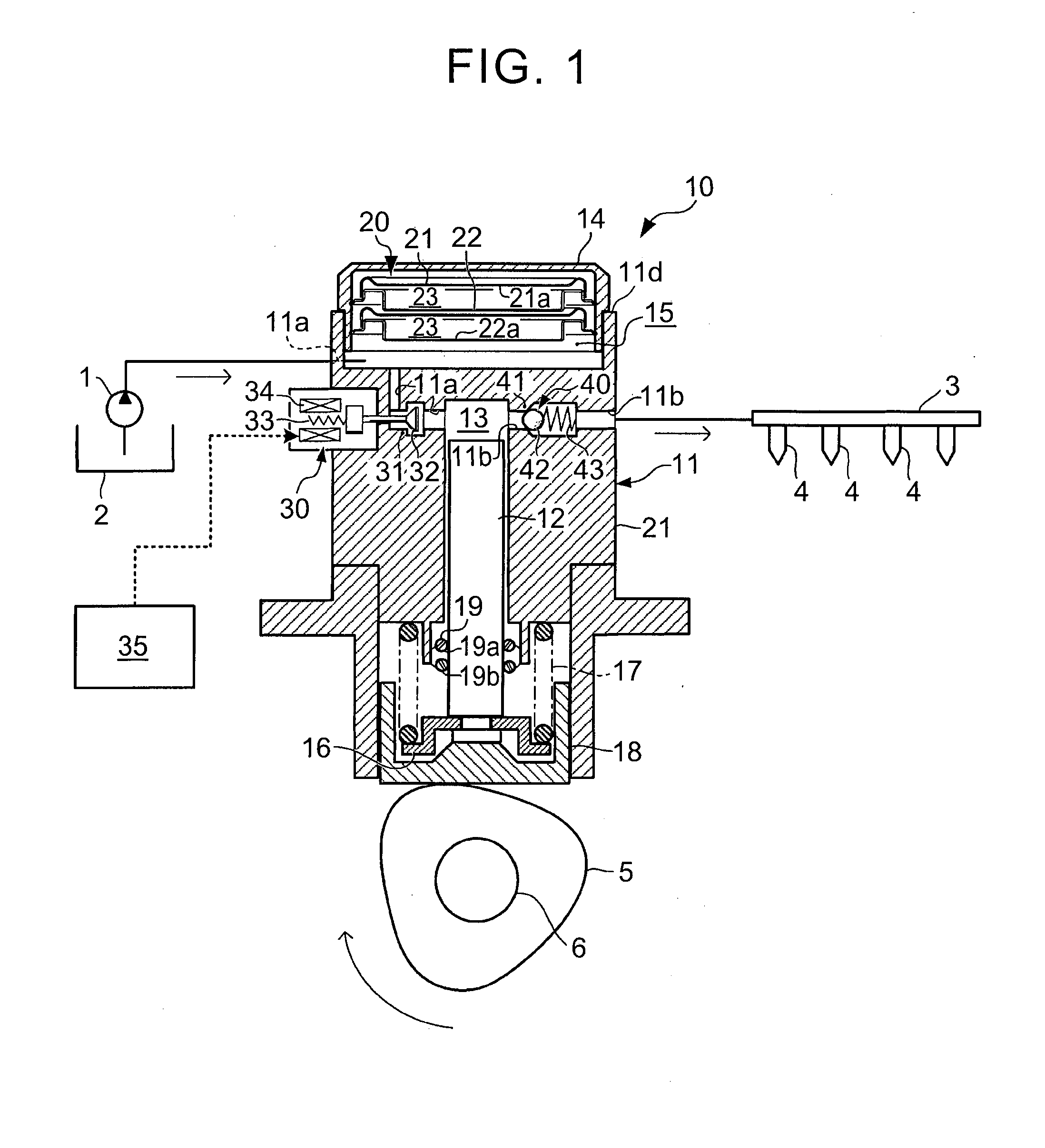
[0042]FIG. 1 illustrates a schematic configuration of a fuel supply system including a high-pressure fuel pump including a pulsation damper according to one embodiment of the present invention. FIGS. 2 to 4 illustrate the pulsation damper according to the one embodiment.

[0043]First described is a schematic configuration of the high-pressure fuel pump according to the present embodiment. A high-pressure fuel pump 10 of the present embodiment as illustrated in FIG. 1 is provided in an internal combustion engine mounted in a vehicle, and discharges a fuel for the engine by pressurizing the fuel to a high pressure that enables cylinder injection. The internal combustion engine is, for example, a multi-cylinder gasoline engine (hereinafter, just referred to as “engine”) of a so-called cylinder injection type or dual injection type that is able to perform cylinder direct fuel injection.

[0044]As illustrated in FIG. 1, the high-pressure fuel pump 10 of the present embodiment includes: a hou...


PUM


Abstract

A pulsation damper (20) includes a first diaphragm (21) and a second diaphragm (22) having a first pressure-receiving film portion (21a) and a second pressure-receiving film portion (22a) and defining a gas chamber (23) between the first pressure-receiving film portion (21a) and the second pressure-receiving film portion (22a) and an annular attachment member (24) configured to support the first diaphragm (21) and the second diaphragm (22). Pressure receiving areas (A1, A2) of the first pressure-receiving film portion (21a) and the second pressure-receiving film portion (22a) are different from each other. The annular attachment member (24) includes a large-diameter annular support portion (24a) formed so as to surround the first pressure-receiving film portion (21a) and to support the first diaphragm (21); a small-diameter annular support portion (24b) formed so as to surround the second pressure-receiving film portion (22a) and to support the second diaphragm (22); and an annular coupling portion (24c) configured to couple the large-diameter annular support portion (24a) with the small-diameter annular support portion (24b) so as to close the gas chamber (23).

Description

BACKGROUND OF THE INVENTION[0001]1. Field of the Invention[0002]The present invention relates to a pulsation damper and a high-pressure fuel pump, and particularly to a pulsation damper including a gas chamber formed by a diaphragm, and a high-pressure fuel pump including the pulsation damper.[0003]2. Description of Related Art[0004]As a pulsation damper for restraining fluid pressure pulsation, a pulsation damper including a diaphragm configured to receive a fuel pressure on one side and a gas chamber formed on the other side of the diaphragm is often used. This type of pulsation damper is attached to a plunger-type high-pressure fuel pump configured to pressure-feed a high-pressure fuel to an internal combustion engine that is able to perform cylinder injection (cylinder direct fuel injection), for example. The pulsation damper is configured to absorb that relatively high-frequency pulsation of an intake-side fuel pressure which is caused along with a pump operation, so as to redu...

Claims


Application Information

Patent Timeline
Patent Type & Authority Applications(United States)
IPC IPC(8): F02M55/04F02M59/44F04B53/00F02M59/10
CPCF02M55/04F04B53/001F02M59/44F02M59/102F02M59/06F02M59/368
Inventor YABUUCHI, TAKEYUKI
Owner TOYOTA JIDOSHA KK
Why Eureka
Try Eureka