Method and Apparatus for Contact Detection in Battery Packs

a battery pack and contact detection technology, applied in secondary cells, cell components, instruments, etc., can solve the problems of 10 w power dissipation, 1 m contact resistance is unacceptable, and the contact resistance will rise, so as to improve the performance of the battery pack, improve the contact resistance, and be easily integrated into the cell supervisor.

Active Publication Date: 2016-06-16
DATANG NXP SEMICON CO LTD
View PDF4 Cites 14 Cited by
  • Summary
  • Abstract
  • Description
  • Claims
  • Application Information

AI Technical Summary

Benefits of technology

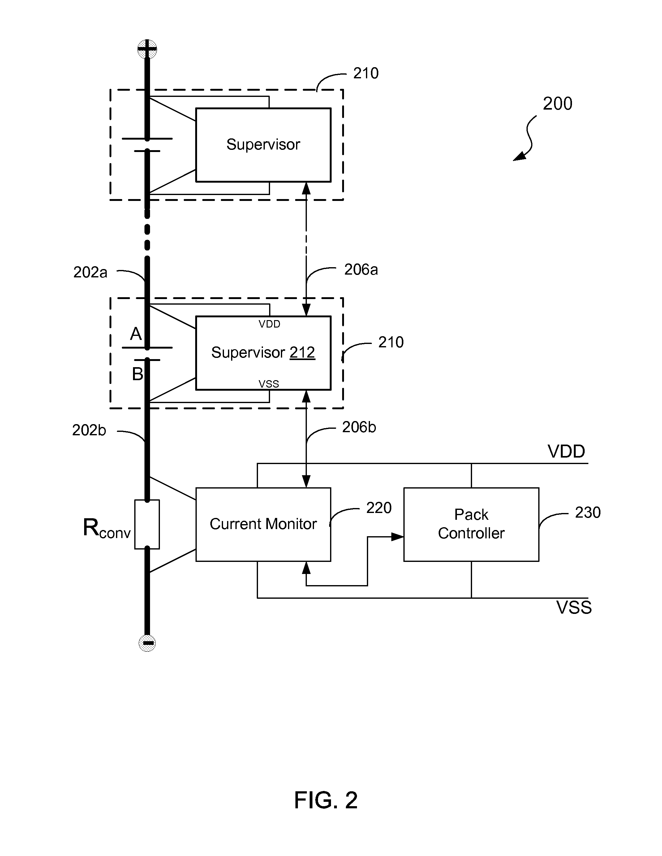
[0013]With this invention, the (onset of) degradation (e.g., corrosion or loosening) of a contact can be detected by the cell supervisor, without the need to add external components or wires to the battery pack. By simply monitoring the voltage difference between the power bar and the corresponding communication line, an increase of the contact resistance can be measured for each individual power bar in the battery pack. All required additional circuitry can be easily integrated into the cell supervisor. Such detection is beneficial to improve the performance of the battery pack, extend the battery lifetime between recharges, and avoid potential damage to the battery pack.

Problems solved by technology

Moreover, this contact resistance will rise if the contact gets corroded, loose, aging, etc.
If the pack current is high, even a contact resistance of just 1 m would be unacceptable.
For example, with a pack current of 100 A, it would give rise to a power dissipation of 10 W, which is undesirable.
Furthermore, a high contact resistance would lead to a hotspot that can severely limit the lifetime of the battery cell involved.
In case of severe corrosion, the temperature rise may even cause a fire or explosion.

Method used


Image

  • Method and Apparatus for Contact Detection in Battery Packs
  • Method and Apparatus for Contact Detection in Battery Packs
  • Method and Apparatus for Contact Detection in Battery Packs

Examples


Embodiment Construction

[0021]The detailed description set forth below in connection with the accompany drawings is intended as a description of exemplary embodiments of the present invention and is not intended to represent the only exemplary embodiments in which the present invention can be practiced. The detailed description includes specific details for the purpose of providing a thorough understanding of the exemplary embodiments of the specification. It will be apparent to those skilled in the art that the exemplary embodiments of the specification may be practiced without these specific details. In some instances, well known structures and devices are shown in block diagram form in order to avoid obscuring the exemplary embodiments presented herein.

[0022]The term “example” or “exemplary” as used throughout this application is only by way of illustration, and not limitation. Further, it will be understood that when an element is referred to as being “connected to” or “coupled to” another element, it ...


PUM

PropertyMeasurementUnit
poweraaaaaaaaaa
voltageaaaaaaaaaa
thresholdaaaaaaaaaa

Abstract

Method and apparatus for contact detection in battery packs are disclosed. The battery pack may comprise at least a first battery cell and a second battery cell, and a power bar for coupling a first electrode of the first battery cell to a second electrode of the second battery cell. The first battery cell comprises a supervisor, which comprises a transmitter / receiver for signal communication with the second battery cell via a communication wire, and a voltage difference detector coupled to the power bar and the communication wire, for detecting a voltage difference between the power bar and the communication wire. The supervisor may indicate degraded contact of the power bar if the detected voltage difference is out of a predetermined threshold range. A battery cell and a method for monitoring a battery pack are also disclosed.

Description

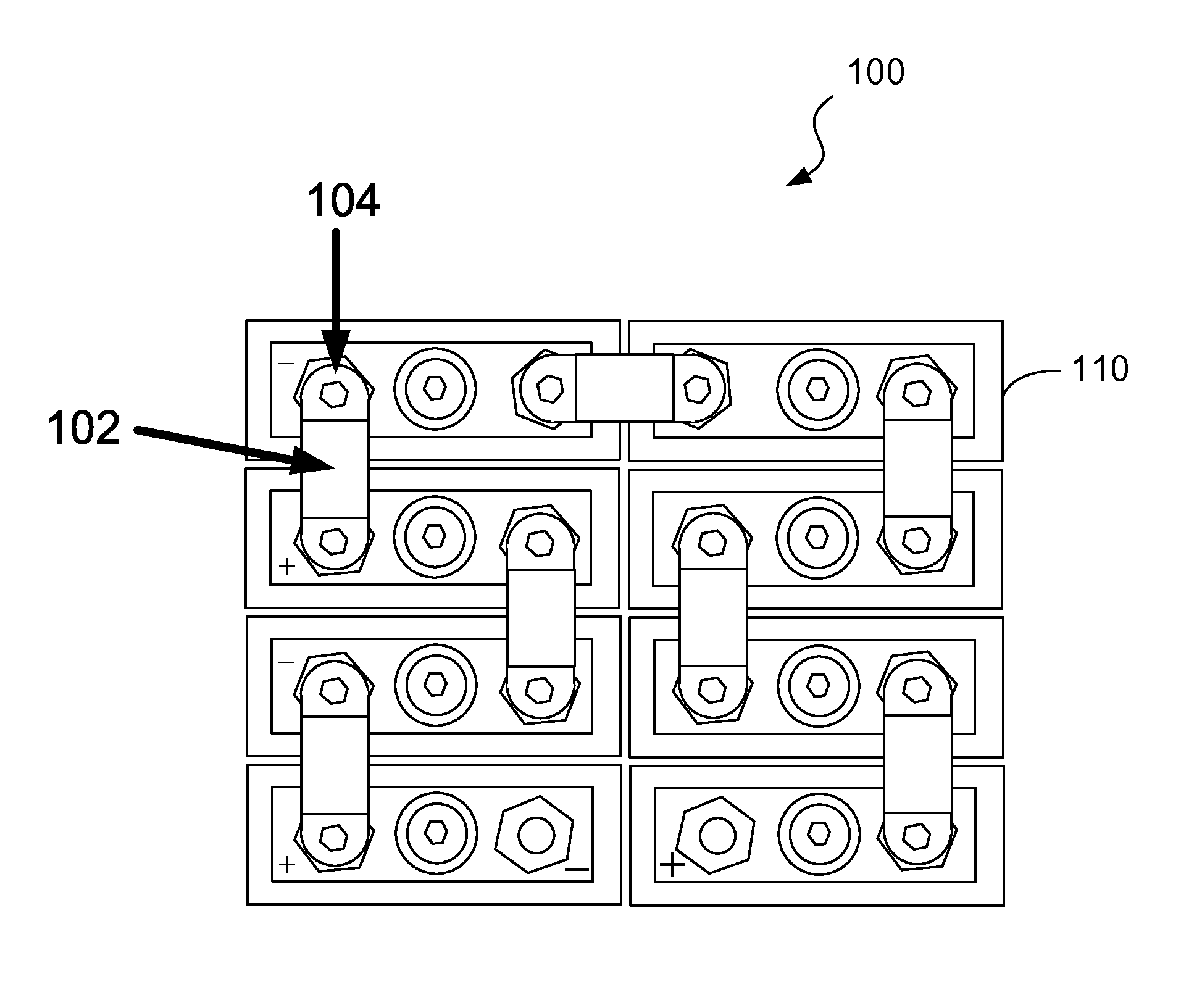
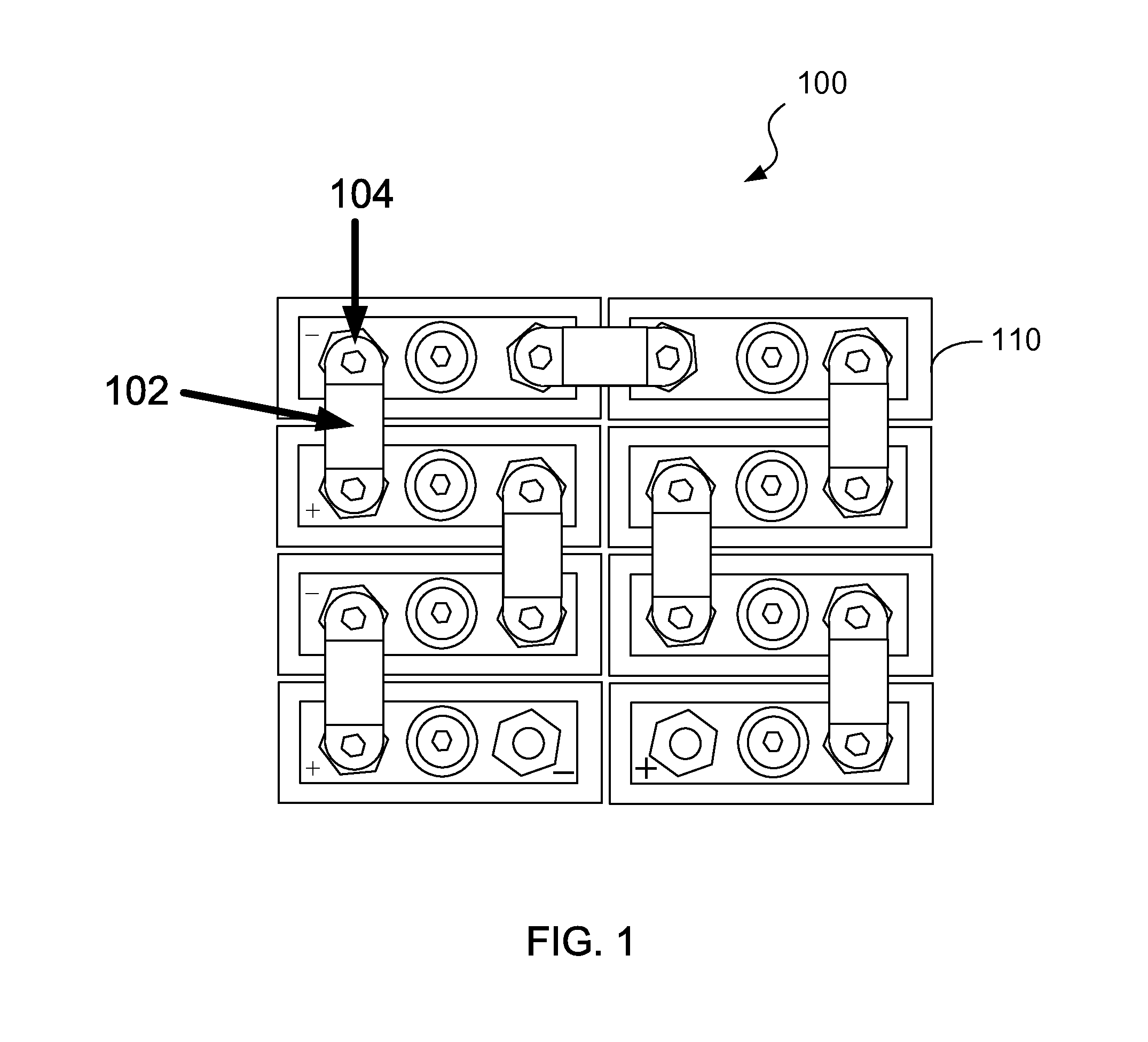
FIELD OF THE INVENTION[0001]This disclosure generally relates to battery packs, and more specifically to method and apparatus for supervision in battery packs.BACKGROUND OF THE INVENTION[0002]Battery packs formed with a number of series-connected battery cells are widely employed for power supply, especially in mobile appliances. As known, in (hybrid) electric vehicles, a battery pack is used to generate a high voltage to drive the motor. In such a battery pack, the number of battery cells are coupled in series by electrically conducting power bars, wherein each power bar can electrically couple a positive electrode of one battery cell to a negative electrode of an adjacent battery cell, e.g., by soldering or bolting.[0003]Each component on a current path in the battery pack is preferably designed to have a small resistance in order to reduce useless power dissipation, especially when a current flowing through the battery cells is large (e.g., several 100 A). Usually, the contact re...

Claims


Application Information

Patent Timeline
Patent Type & Authority Applications(United States)
IPC IPC(8): H01M10/48G01R31/36H01M50/209H01M50/51H01M50/517
CPCH01M10/482G01R31/3679G01R31/3696H01M10/425G01R31/382G01R31/68Y02E60/10H01M50/51H01M50/517H01M50/209H01M2010/4278
Inventor LAMMEREN, JOOP VAN
Owner DATANG NXP SEMICON CO LTD
Why Eureka
Try Eureka