
Adjustable row unit deck plate for a header of an agricultural harvester

a technology for harvesters and headers, applied in the field of headers, can solve the problems of individual deck plates not maintaining parallelism, reducing crop yield, and aft end of crop receiving gaps clogging with stalk debris, so as to reduce the clogging of debris, and reduce the clogging of the aft end of the crop receiving gap. the effect of increasing the strength of the mechanism and reducing the clogging

Active Publication Date: 2016-06-23
BLUE LEAF I P INC
View PDF14 Cites 12 Cited by
  • Summary
  • Abstract
  • Description
  • Claims
  • Application Information

AI Technical Summary

Benefits of technology

The patent describes a new design for a row unit that is better at picking and stripping crops from their stalk, and less likely to get blocked with debris. It uses a unique rockshaft mechanism that is independent of other adjustments made to the unit. This allows for easier cleaning and ensures that the deck plate stays clean and moves freely. This design also eliminates the need for a slide mechanism, which is commonly used in conventional row units. Overall, the new design is simpler, more efficient, and more reliable than existing rows.

Problems solved by technology

A disadvantage of presently available headers is that individual deck plates do not maintain their parallelism as crop is being harvested.
Conversely, if the fore regions of the deck plates diverge too severely, then they may prevent certain ears of crop from being stripped from the stalk by the deck plates, whereby crop is left on the stalk as it is pulled under by the stalk rolls, thereby also reducing crop yield.
Furthermore, if the fore regions of the deck plates are too divergent, then the aft end of the crop receiving gap will clog with stalk debris which requires periodic stoppage of the harvesting operation in order to remove the crop matter from between the deck plates.
Moreover, parallelism between deck plates is not always maintained when the control linkage is extended and retracted.

Method used


Image

  • Adjustable row unit deck plate for a header of an agricultural harvester
  • Adjustable row unit deck plate for a header of an agricultural harvester
  • Adjustable row unit deck plate for a header of an agricultural harvester

Examples


Embodiment Construction

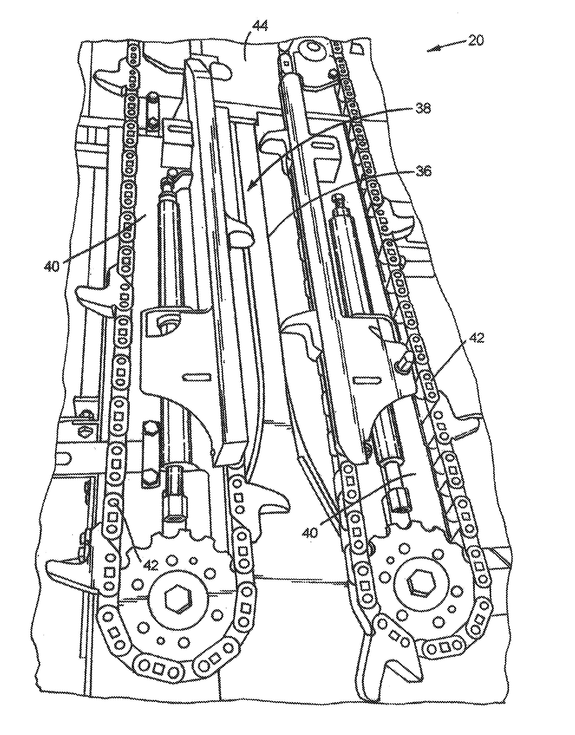
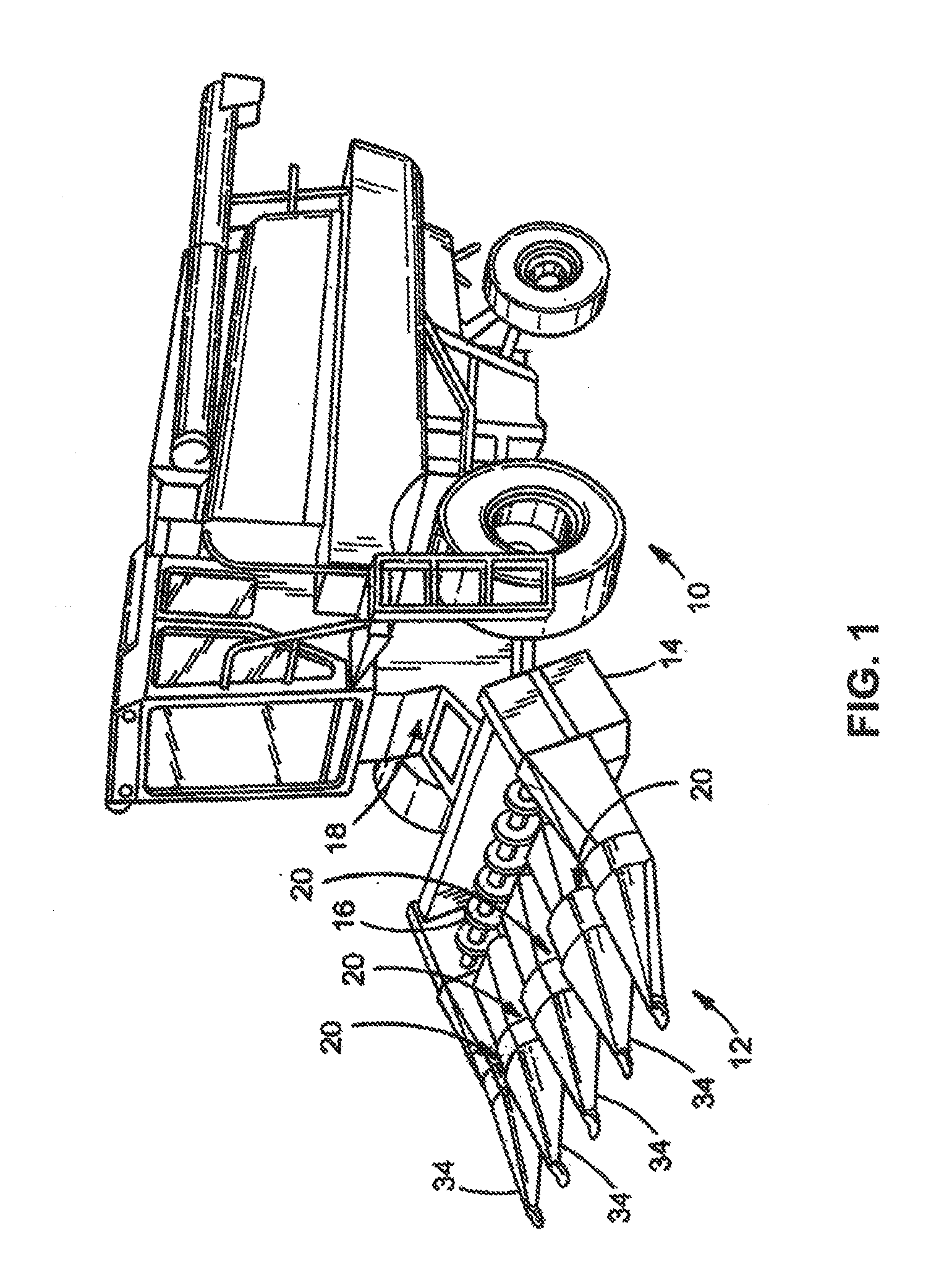
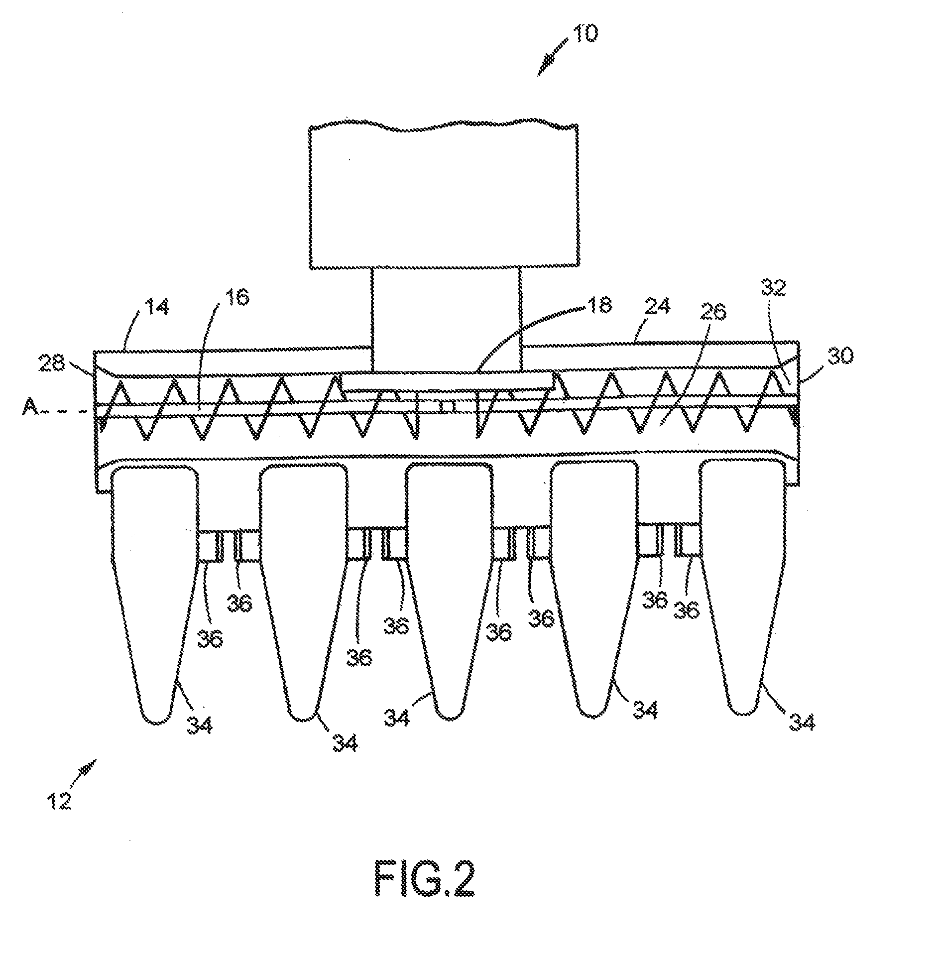
[0024]Reference will now be made in detail to the various aspects of the subject application illustrated in the accompanying drawings. Wherever possible, the same or like reference numbers will be used throughout the drawings to refer to the same or like features. It should be noted that the drawings are in simplified form and are not drawn to precise scale. In reference to the disclosure herein, for purposes of convenience and clarity only, directional terms such as top, bottom, left, right, above, below and diagonal, are used with respect to the accompanying drawings. Such directional terms used in conjunction with the following description of the drawings should not be construed to limit the scope of the subject application in any manner not explicitly set forth. Additionally, the term “a,” as used in the specification, means “at least one.” The terminology includes the words above specifically mentioned, derivatives thereof, and words of similar import.

[0025]Referring now to the...


PUM

PropertyMeasurementUnit
sizeaaaaaaaaaa
strengthaaaaaaaaaa
weightaaaaaaaaaa

Abstract

An adjustable row unit for a header of an agricultural harvester is disclosed. The row unit includes a movable deck plate. The deck plate is connected to a row unit frame extending in a fore and aft direction of the header. A pivot shaft extends in the fore and aft direction and is pivotably connected to the row unit frame and the deck plate. A rocker assembly connects the deck plate to the pivot shaft for enabling selective positioning of the deck plate relative to the row unit frame in a direction substantially transverse to the fore and aft direction and whereby parallelism between the deck plate and an opposing deck plate is maintained throughout the crop harvesting process.

Description

BACKGROUND[0001]The subject application relates generally to a header for use with agricultural harvesters. In particular, the subject application relates to an adjustable row unit deck plate for an agricultural harvester header.[0002]The header of an agricultural harvester or combine is provided with row dividers and associated hoods for directing rows of corn stalks to downstream separation devices known as row units. The row units include stalk receiving slots or gaps and stripping plates, snapping rolls, and opposed rearwardly moving gathering chains. Thus, e.g., following separation of ears from stalks by the snapping rolls and stripping plates (also known as stalk rolls and deck plates, respectively), the separated ears are delivered by the gathering chains to an auger or other suitable conveyor which conveys the harvested ears to a feederhouse of the combine. Harvested ears are then processed to the combine's inner chambers for downstream processing.[0003]Row unit frames are ...

Claims


Application Information

Patent Timeline
Patent Type & Authority Applications(United States)
IPC IPC(8): A01D45/02
CPCA01D45/023A01D41/14A01D45/021A01D47/00
Inventor WALKER, ERIC L.
Owner BLUE LEAF I P INC
Learn More