
Dental treatment implement with anomaly site detection function

a technology of anomalous site and implement, which is applied in the field of dental treatment implement with anomalous site detection function, can solve the problems that the plaque detection device does not have a treatment function for the adhesion site of dental plaque, and achieves the effect of clear color image, efficient and reliable implementation, and efficient and reliable implementation

Inactive Publication Date: 2016-06-23
YOSHIDA DENTAL MFG
View PDF3 Cites 4 Cited by
  • Summary
  • Abstract
  • Description
  • Claims
  • Application Information

AI Technical Summary

Benefits of technology

The present invention provides a dental treatment implement with an anomaly site detection function. This is achieved by using a color camera module group including three color camera modules, each with different wavelengths of excitation light, and a light emission / image pick-up optical system. One of the color camera modules is detachably mounted in a specific position, allowing for efficient and reliable implementation of MI in treatment of dental caries and PMTC in brushing guidance and treatment of a row of teeth. The dental treatment implement may also include an angle-type or straight-type micromotor handpiece or an angle-type or straight-type air-turbine handpiece, with each color camera module detachably arranged in a position able to be exposed to the outside by disassembly in the inside of the handpiece body.

Problems solved by technology

The plaque detection device, however, does not have a treatment function for a dental plaque adhesion site or the like, though having a detection function therefor.

Method used


Image

  • Dental treatment implement with anomaly site detection function
  • Dental treatment implement with anomaly site detection function
  • Dental treatment implement with anomaly site detection function

Examples


embodiments

[0037]A dental treatment implement with an anomaly site detection function according to an embodiment of the present invention will be described in detail hereinafter with reference to accompanying drawings.

first embodiment

[0038]A dental treatment implement with, an anomaly site detection function according to a first embodiment is applied to a micromotor-driven-type handpiece which is a kind of dental treatment instrument.

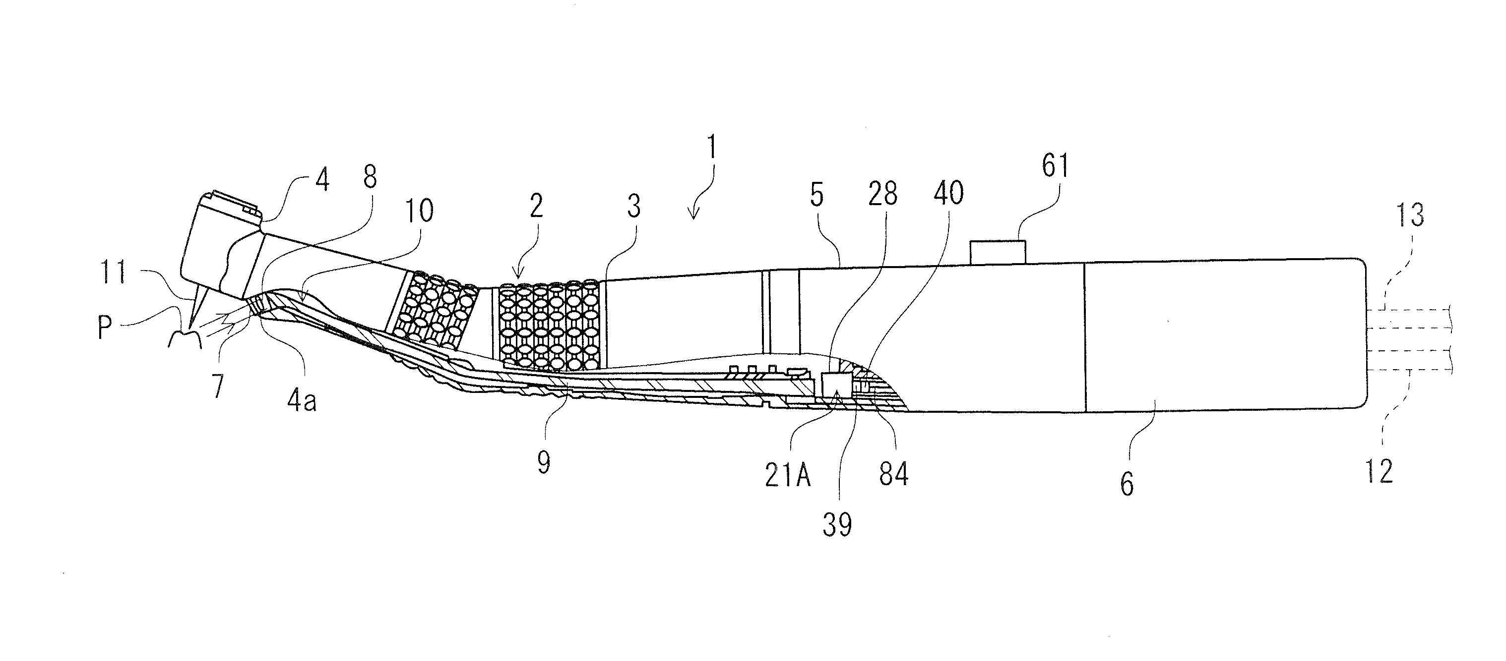
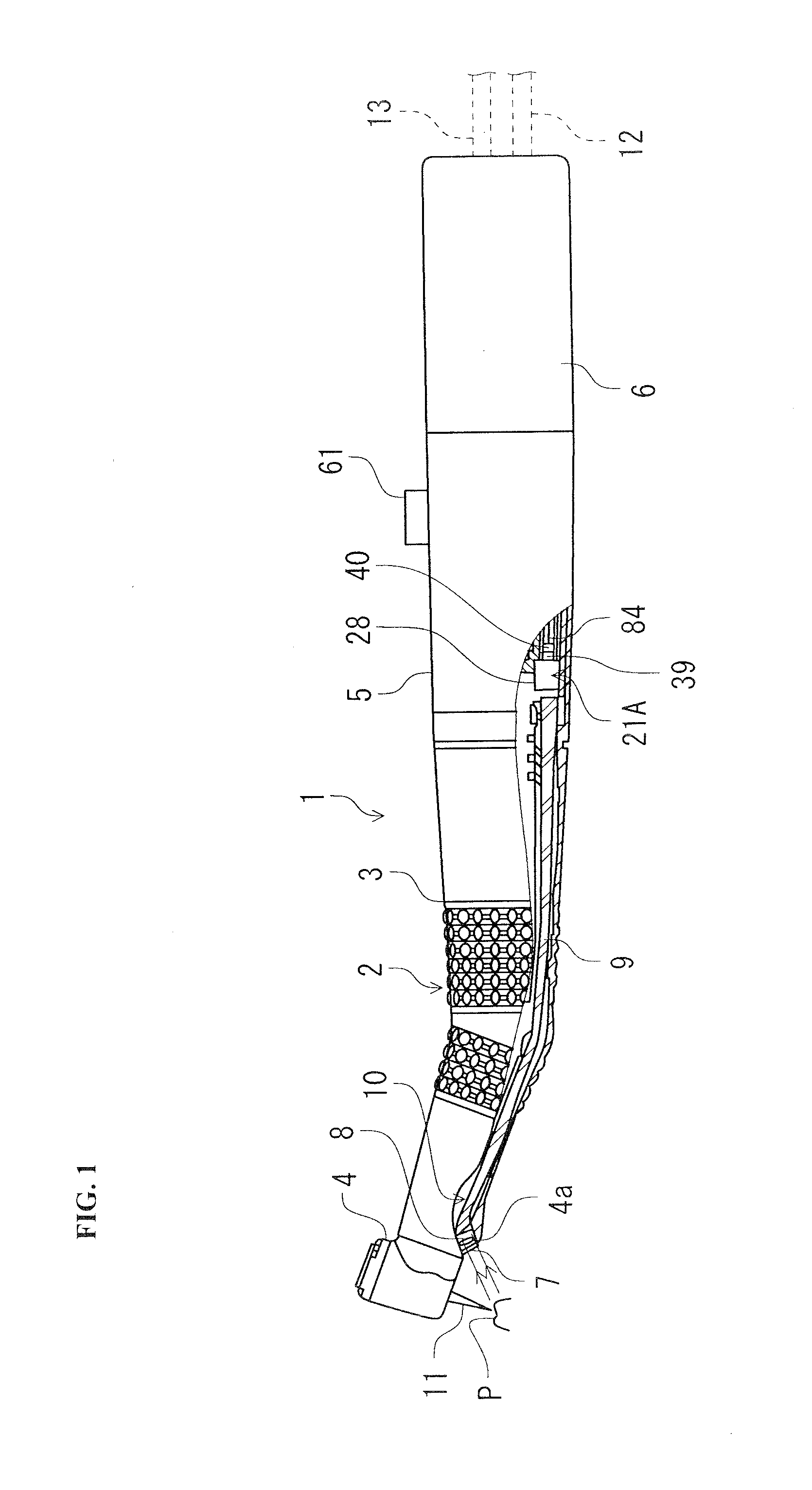
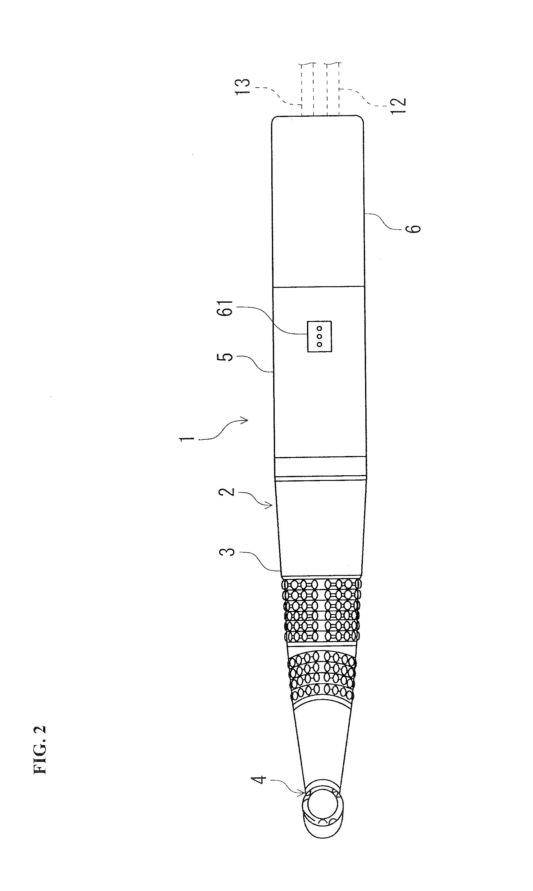
[0039]As illustrated in FIGS. 1 and 2, the micromotor handpiece 1 with the anomaly site detection function according to the first embodiment (hereinafter, referred to as “handpiece 1 of the first embodiment”) includes: a handpiece body 2 which includes a grip part 3 having a head part 4, where a cutting tool 11 for treating an affected area P is detachably mounted, on the distal end side and a coupling part 5 which is formed in a substantially cylindrical shape and detachably coupled to the grip part 3 and which detachably houses whole of one of color camera modules (for example, a first color camera module 21A) of a color camera module group 21 composed of three kinds of color camera modules, i.e., first to third color camera modules 21A, 21B, and 21C, having detachable compatibili...

second embodiment

[0111]Subsequently, a second embodiment of the present invention will be described with reference to FIGS. 20 and 21.

[0112]A dental treatment implement with an anomaly site detection function of the second embodiment is applied to an air-turbine-type handpiece which is a kind of dental treatment instrument.

[0113]In the air-turbine handpiece 1B with an anomaly site detection function of the second embodiment (hereinafter, referred to as “handpiece 1B of the second embodiment”), the same elements as in the handpiece 1 of the first embodiment are denoted by the same reference numerals.

[0114]As Illustrated in FIGS. 20 and 21, the handpiece 1B of the second embodiment includes: a handpiece body 2 which includes a grip part 3 having a head part 4, where a cutting tool 11 for treating an affected area P is detachably mounted, on the distal end side and a coupling part 5 which is formed in a substantially cylindrical shape and detachably coupled to the grip part 3; and a dental tube part 91...


PUM


Abstract

[Problem] The present invention provides a dental treatment implement with an anomaly site detection function, capable of accurately detecting an anomaly site on a tooth and gingiva (marginal part) in an oral cavity using an image, accurately treating the site on the basis of the image, and performing MI and PMTC in an efficient and reliable manner.[Solution] The present invention includes: a micromotor handpiece 1 with an anomaly site detection function, the micromotor handpiece 1 being a dental treatment implement for treating an anomaly site in an oral cavity: a color camera module group 21 including a plurality of color camera modules 21A, 21B, and 21C, wherein each color camera module is constructed by integrating a light emission means including a light source unit 21A, 27B, or 27C for at least emitting excitation light for producing fluorescent light at an anomaly site in the oral cavity and an image pick-up means for picking up an image of the anomaly site and surrounding sites in the oral cavity as a color image, wherein the wavelengths of the excitation light emitted from the light source units 27A, 27B, and 27C are different from each other, and wherein, one of the color camera modules is detachably mounted in a specific position on the micromotor handpiece 1 with the anomaly site detection function; and a light emission / image pick-up optical system 10 for radiating the excitation light from the light source unit 27A, 27B; or 27C of the color camera module 21A, 21B, or 21C mounted in the specific position coward the anomaly site and guiding the fluorescent light produced at the anomaly site to a camera unit 31 of the color camera module 21A, 21B, or 21C.

Description

TECHNICAL FIELD[0001]The present invention relates to a dental treatment implement with an anomaly site detection function, more specifically, to a dental treatment implement with an anomaly site detection function capable of performing therapy, treatment, or the like of the anomaly site while viewing an anomaly site on a tooth such as, for example, a dental caries site or a dental plaque adhesion site by using an image.BACKGROUND ART[0002]Conventionally, in the field of the dental treatment, a dentist performs therapy or treatment such as the excision of a dental caries site or the removal of dental plaque and tartar by operating various dental treatment implements such as a dental air-turbine handpiece equipped with tools or the like, a micromotor handpiece, a scaler, and a three-way syringe and further determines the site concerned by using a dental detection device for detecting a dental caries site and a dental plaque adhesion site.[0003]The foregoing dental treatment implement...

Claims


Application Information

Patent Timeline
Patent Type & Authority Applications(United States)
IPC IPC(8): A61B5/00A61C1/06A61B1/06A61C1/12A61C3/02A61C1/05A61C1/10
CPCA61B5/0071A61B5/0088A61C1/05A61B1/0646A61C1/10A61C1/12A61C3/02A61C1/06A61B1/24A61B1/042A61B1/07A61C1/088A61B1/043A61B1/0638
Inventor HASEGAWA, TAKESHIYAMANAKA, MICHIZO
Owner YOSHIDA DENTAL MFG
Learn More