Method of manufacturing polarizing plastic lens

Active Publication Date: 2016-06-23
EHS LENS PHILIPPINES
View PDF2 Cites 12 Cited by
  • Summary
  • Abstract
  • Description
  • Claims
  • Application Information

AI Technical Summary

Benefits of technology

[0036]In an embodiment, adhesive is discharged directly upward from a discharge nozzle positioned directly beneath a spot where an adhesive column is being formed. Thus, even when the spots at which adhesive columns are being formed are on the rim portion of the molding surface of an upper mold having an inclined surface, the position and height of adhesive column formation can be readily controlled. Discharging adhesive by such a method can prevent adhesive from adhering in an inclined manner to the molding surface of the upper mold and readily permit the formation of adhesive that is disposed vertically downward. This is advantageous for efficiently obtaining a polarizing plastic lens of high quality of external appearance. In above-cited Japanese Unexamined Patent Publication (KOKAI) No. 2012-198389, the adhesive is applied on the horizontal flange portion of the molding surface of a casting mold. By contrast, in the above method, it is possible to readily form adhesive columns of controlled position and height even without using a mold having a horizontal flange surface at the application positions in spots where adhesive columns are formed, thereby permitting the use of a casting mold for common meniscu

Problems solved by technology

However, in Japanese Unexamined Patent Publication (KOKAI) No. 2009-3303, because resin discharge and curing are conducted in parallel, the polarizing film tends to partially deform and the needle tends to clog.
When the adhesive tilts, the polarizing film is not kept level,

Method used


Image

  • Method of manufacturing polarizing plastic lens
  • Method of manufacturing polarizing plastic lens
  • Method of manufacturing polarizing plastic lens

Examples


Embodiment Construction

[0051]The present invention will be described through specific implementation modes below with reference to the drawings. However, the present invention is not limited to the embodiments shown in the drawings. Portions described in the drawings have been shown suitably enlarged or reduced so as to be identifiable.

[0052]

[0053]The structure of the polarizing plastic lens will be described below with reference to the drawings.

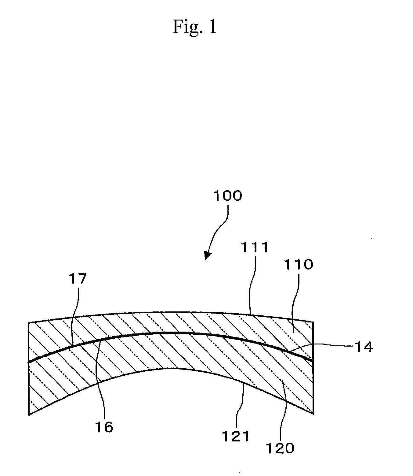
[0054]FIG. 1 is a sectional view of a polarizing plastic lens relating to the present implementation mode. Polarizing plastic lens 100 relating to the present implementation mode is a semifinished eyeglass lens. As shown in FIG. 1, the structure includes a polarizing film 14 positioned between two lens substrates 110 and 120. In lens substrate 110, the surface on the opposite side from the surface opposing polarizing film 14 is a convex surface 111. In lens substrate 120, the surface on the opposite side from the surface opposing polarizing film 14 is a concave su...


PUM

PropertyMeasurementUnit
Viscosityaaaaaaaaaa
Viscosityaaaaaaaaaa

Abstract

Method of manufacturing polarizing plastic lens, including an upper mold positioning step of positioning an upper mold so that a nonmolding surface faces up and a molding surface faces down, an adhesive column forming step of discharging a thixotropic curable adhesive from a nozzle beneath the upper mold to form adhesive columns on the molding surface of the upper mold, a step of bonding the upper mold and a polarizing film, an adhesive column curing step of subjecting the adhesive columns to a curing treatment, a casting mold assembling step of assembling a casting mold having a cavity within which the polarizing film has been positioned with the upper mold to which the polarizing film has been bonded, a lower mold positioned opposite the upper mold so as to sandwich the polarizing film, and a sealing member maintaining a spacing between the upper mold and lower mold, and a polymerizing and curing step of casting a curable composition into the cavity, and polymerizing and curing the curable composition that has been cast to provide a polarizing plastic lens within which the polarizing film is positioned.

Description

CROSS-REFERENCE TO RELATED APPLICATIONS[0001]This application claims the benefit of priority to Japanese Patent Application No. 2012-250034 filed on Nov. 14, 2012, which is expressly incorporated herein by reference in its entirety.TECHNICAL FIELD[0002]The present invention relates to a method of manufacturing a polarizing plastic lens. Background art[0003]Polarizing lenses are often employed as lenses for nonprescription sunglasses (including fashion glasses) to protect the eyes because they function to block light. They are also employed as prescription eyeglass lenses.[0004]The polarizing lenses described in Japanese Unexamined Patent Publication (KOKAI) Nos. 2009-3303 and 2012-198389 (which are expressly incorporated herein by reference in their entirety) are polarizing lenses with polarizing films embedded within them. They are manufactured by casting a curable composition around a polarizing film, heating, and curing (called the casting method or casting polymerization method)...

Claims


Application Information

Patent Timeline
IPC IPC(8): B29D11/00
CPCB29D11/00413B29D11/00442B29K2629/04B29K2995/0034B29D11/00644
Inventor IHARA, MASAKISHIMIZU, HIROSHIITO, YOSHINOBUSHIMIZU, TOSHIHIKOTONOUCHI, KENICHI
Owner EHS LENS PHILIPPINES
Why Eureka
Try Eureka