Pergola Cover
a technology for pergolas and roofs, applied in the field of pergola covers, can solve the problems that retractable awnings may not be suitable for use with free-standing structures
- Summary
- Abstract
- Description
- Claims
- Application Information
AI Technical Summary
Benefits of technology
Problems solved by technology
Method used
Image
Examples
first embodiment
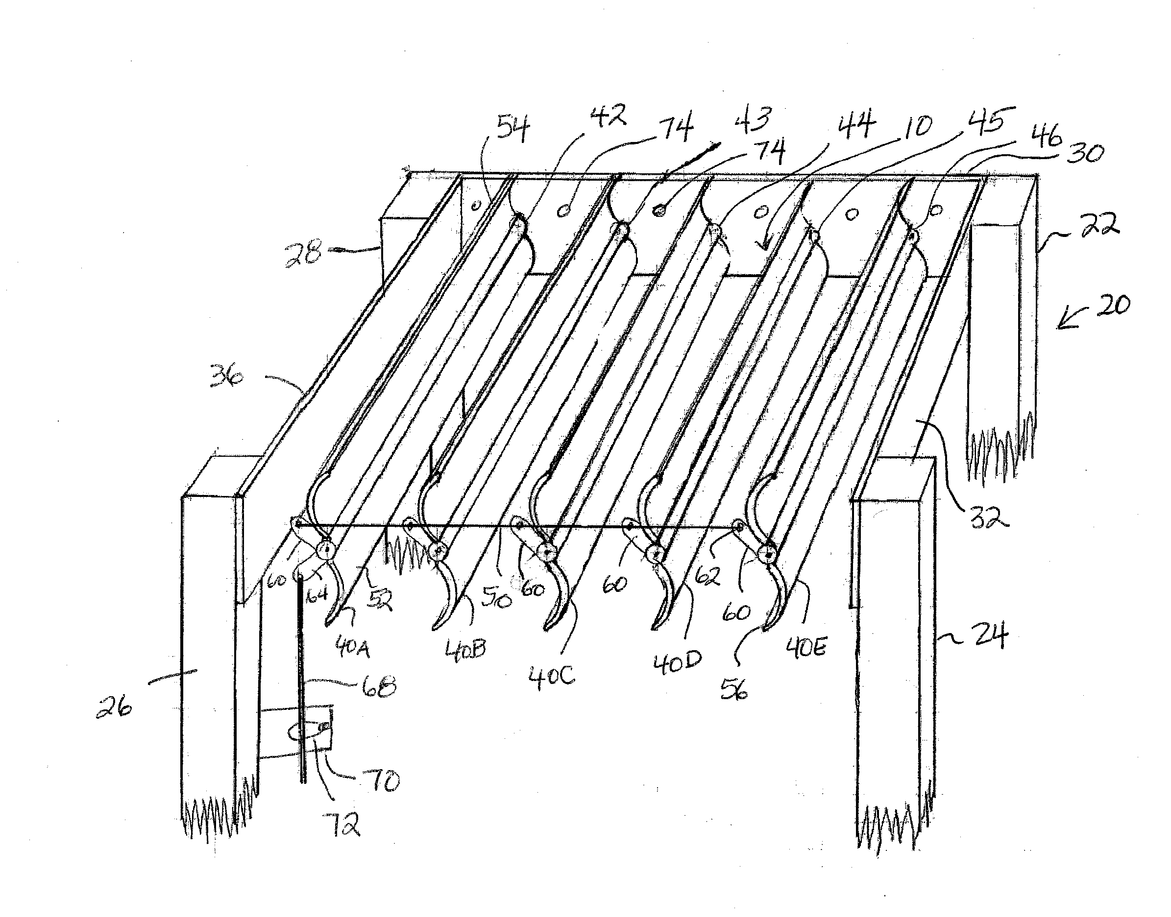
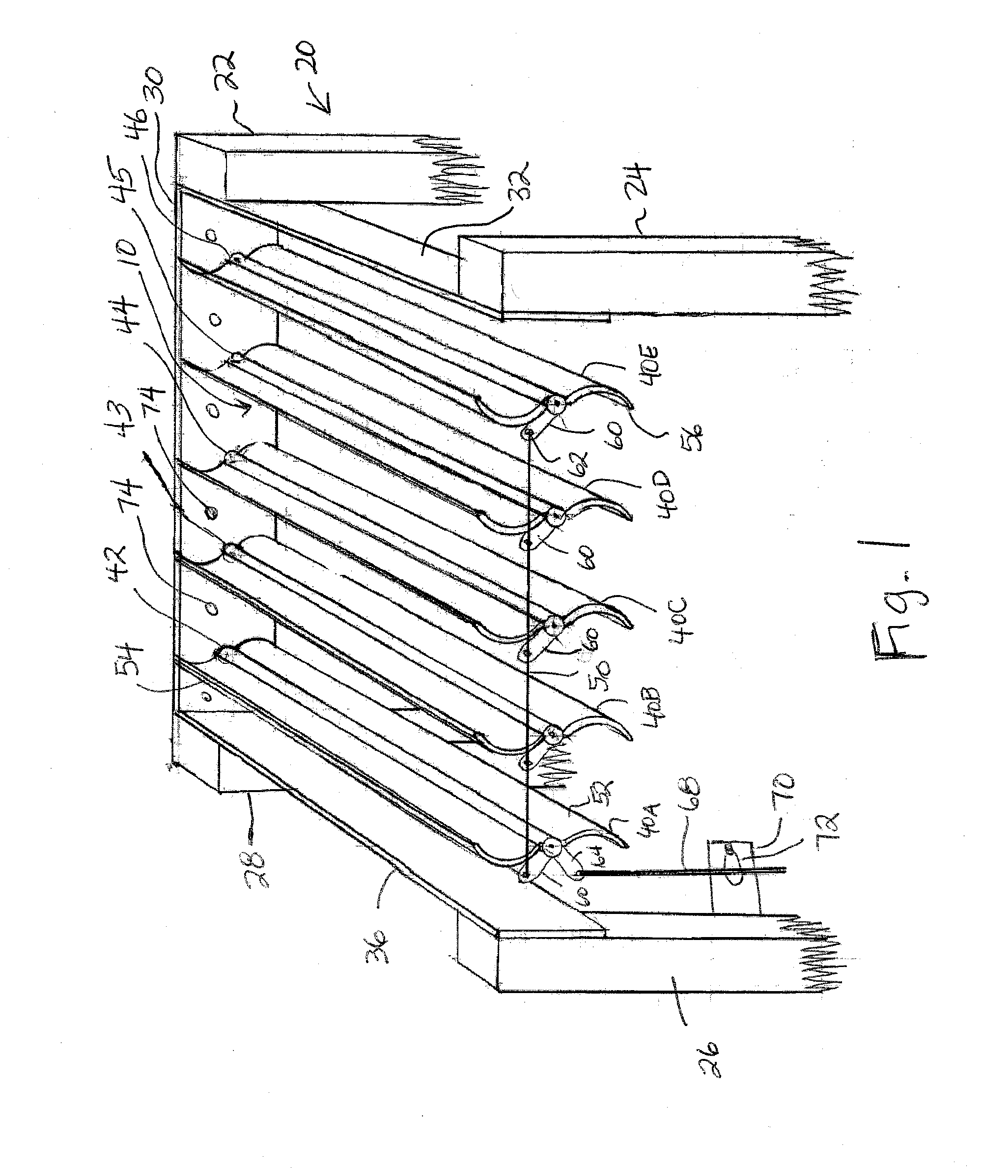
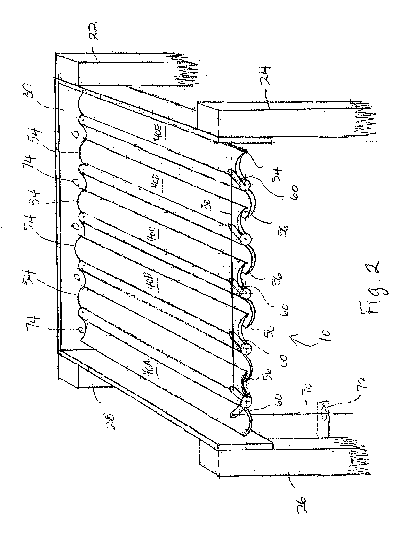
[0014]Turning now to the drawings in more detail, numeral 10 designates the cover system according to this invention. The system 10 is configured to fit in a covering relationship over a structure 20. The structure 20 comprises a plurality of upright vertical posts or vertical supports 22, 24, 26, and 28 spaced apart to form a rectangular or square frame supports. Cross beams extend between upper ends of the vertical posts 22, 24, 26, and 28. While only three cross beams 30, 32, and 36 are shown in FIG. 1, it will be understood that a forth cross beam is positioned between the upright posts 24 and 26 in a parallel relationship to the cross beam 30. For clarity, the fourth cross beam was omitted from the drawings. The covering system 10 is configured to fit between the cross beams of the structure 20. The covering system 10 comprises a plurality of parallel slat assemblies 40 (40A, 40B, 40C, 40D, 40E, etc.) mounted on pivotal shafts 42, 43, 44, 45, and 46, which are rotationally supp...
second embodiment
[0021]Turning now to the covering system of the present invention illustrated in FIGS. 3 and 4, the covering system is designated by numeral 100. In this embodiment, the slat assemblies 102 (102A, 102B, 102C, and 102D) comprise a pair of elongated slat members 104, 106 pivotally attached to a common shaft 108 along their longitudinal upper edges. A hinge 103 supports the slat assemblies 102 in a pivotal relationship on the shaft 108. The slat assemblies 102 are mounted in a parallel relationship to each other and to longitudinal axes of the cross beams 32 and 36.
[0022]The slat members 104, 106 have a substantially J-shaped profile and are mirror images of each other. The upwardly turned lower edges 105 of the slat members 104 face toward to cross beam 36, while the upwardly turned lower edge 110 of the slat members 106 face toward the cross beam 32. Each slat member 104 has a curved bottom 107, and each slat member 106 has a curved bottom 109 with a curvature radius of the bottom 10...
PUM
 Abstract
Description
Claims
Application Information
 - R&D
- Intellectual Property
- Life Sciences
- Materials
- Tech Scout
- Unparalleled Data Quality
- Higher Quality Content
- 60% Fewer Hallucinations
Browse by: Latest US Patents, China's latest patents, Technical Efficacy Thesaurus, Application Domain, Technology Topic, Popular Technical Reports.
© 2025 PatSnap. All rights reserved.Legal|Privacy policy|Modern Slavery Act Transparency Statement|Sitemap|About US| Contact US: help@patsnap.com


