Method of Digitally Printing and System Therefor

a digital printing and printing system technology, applied in the field of digital printing, can solve the problems of increasing the viscosity of the liquid dispersion, difficult to remove such residues, and liquid with a non-uniform distribution of marking particles, so as to facilitate the removal of excess liquid development and improve the treatment process

Inactive Publication Date: 2016-06-23
XEIKON MFG NV
View PDF4 Cites 3 Cited by
  • Summary
  • Abstract
  • Description
  • Claims
  • Application Information

AI Technical Summary

Benefits of technology

[0013]It is desired to improve the treatment process further, so as to facilitate the removal of excess liquid development dispersion from the development member, in a form that does not harm the recycling of the development dispersion.

Problems solved by technology

Thus, the removal of such a residue can be quite challenging.
Particularly, marking particles in the liquid developer dispersion tend to form lumps in the dispersion resulting in a liquid with a non-uniform distribution of marking particles.
This is called caking and often results in an increase of the viscosity of the liquid dispersion.
The removal of the liquid toner residue starts then to be problematic.
As a result, liquid toner residue could remain on the development roller, which constitutes a contamination and may lead to a non-uniform distribution of fresh developer dispersion resulting in a ghost image and or image quality that is not perfect, in other words incorrect.
Specific examples of issues are density instability and incorrect reproduction of fine lines.
Removal of the toner residue by a removal device may reduce the issue, but is not known to solve the issue completely.
It is therefore a major problem to solve the caking issue.
This compression results in absorption of the liquid toner residue in the loosening member, and particularly the rubbing portion thereof.

Method used


Image

  • Method of Digitally Printing and System Therefor
  • Method of Digitally Printing and System Therefor
  • Method of Digitally Printing and System Therefor

Examples


Embodiment Construction

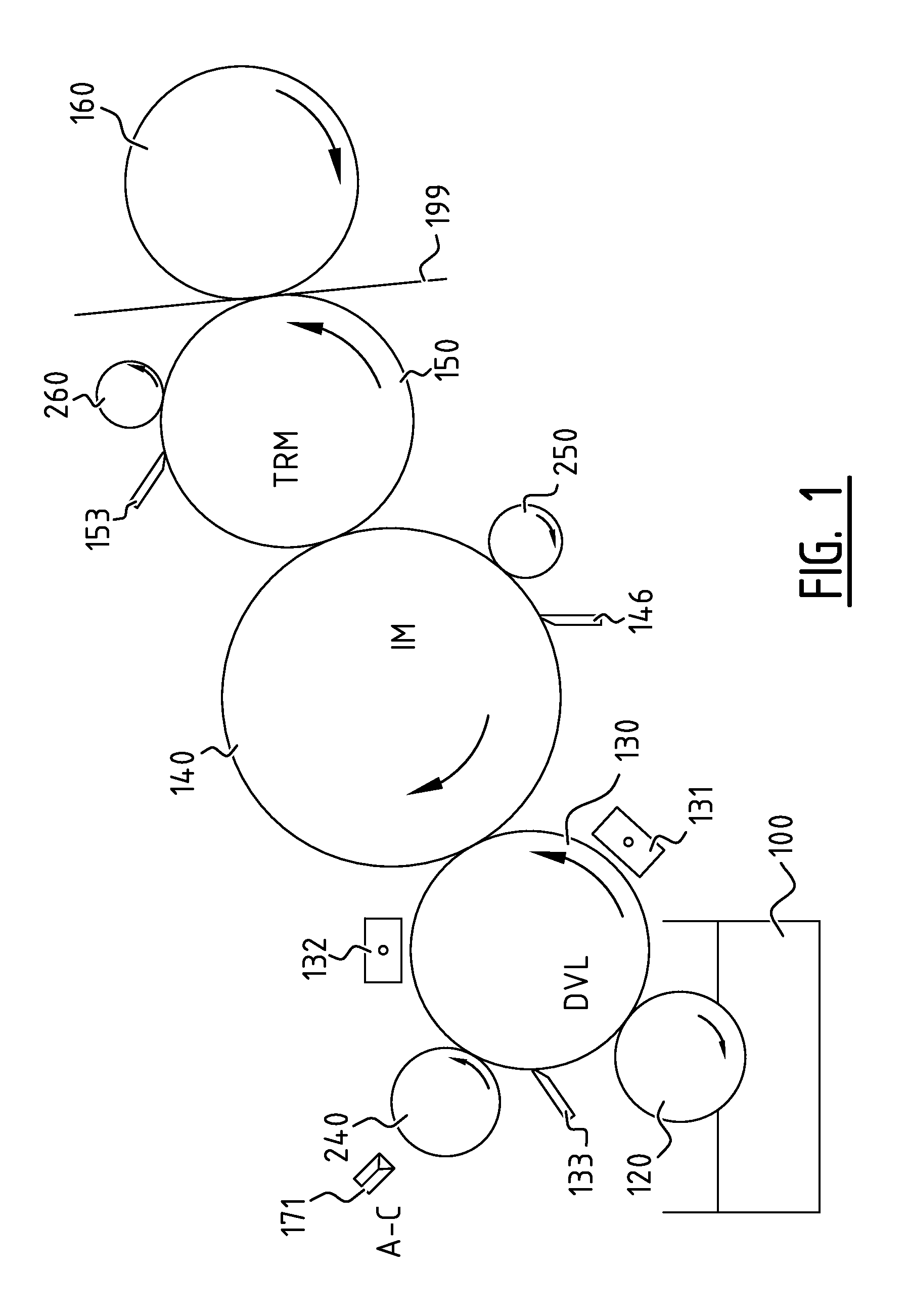
[0057]The Figures are not drawn to scale and purely diagrammatical in nature. Equal reference numerals in different Figures refer to equal or corresponding features.

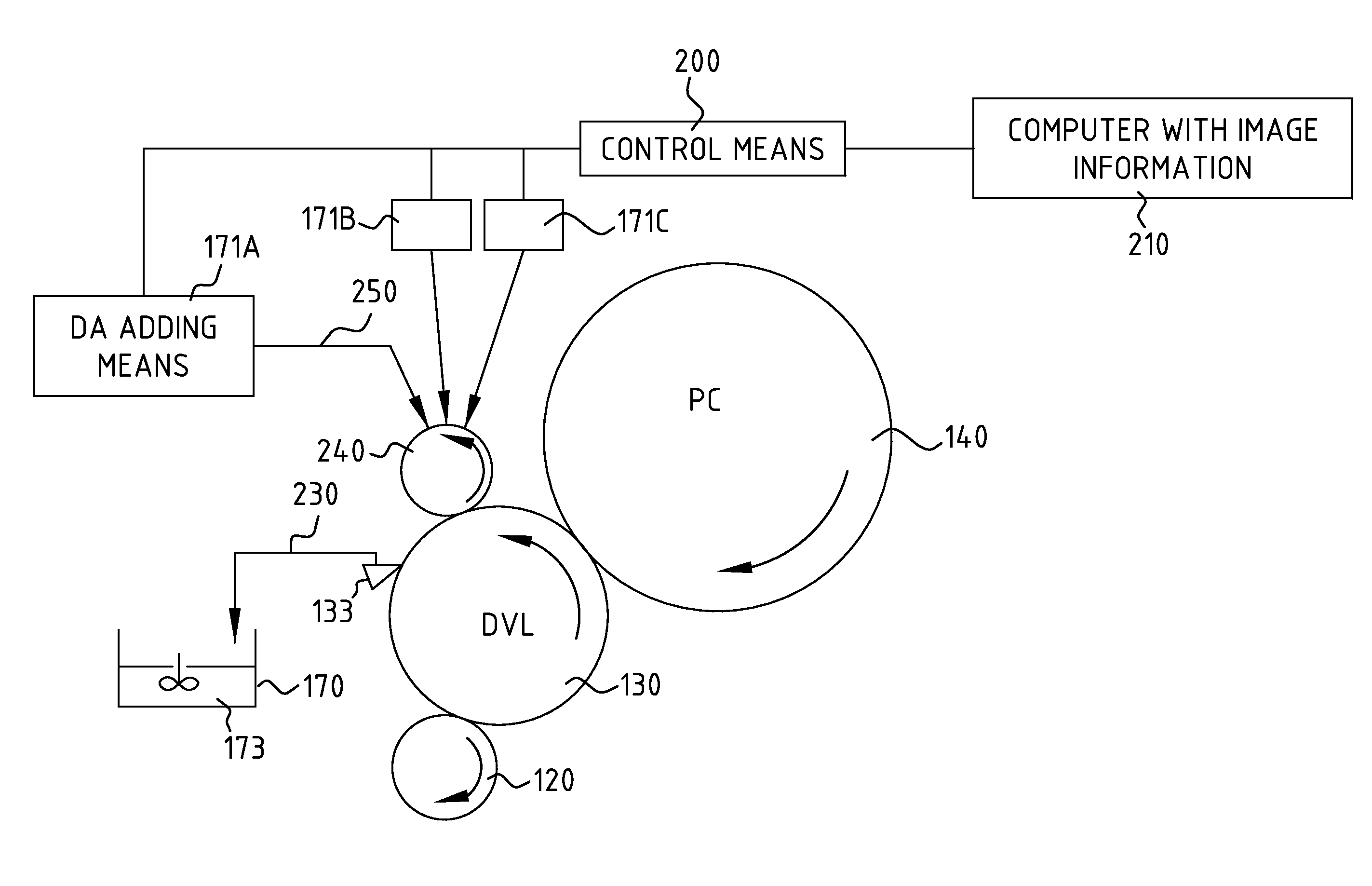
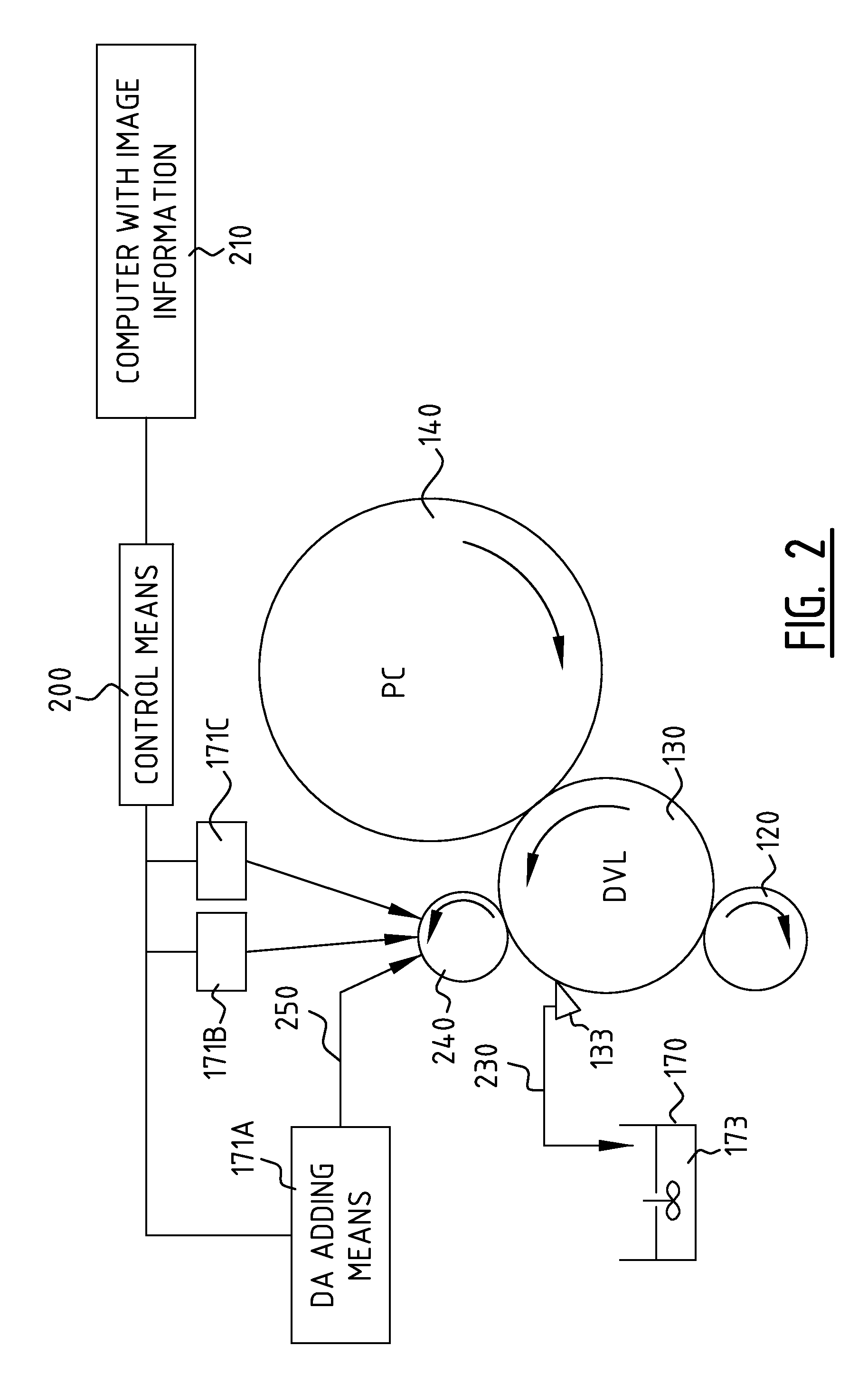
[0058]FIG. 1 illustrates diagrammatically a first embodiment of a digital printing apparatus of the invention, comprising a reservoir 100, a feed member 120, a developer member 130, an imaging member 140, a intermediate member 150 and a support member 160. A substrate 199 is transported between intermediate member 150 and support member 160. Both the development member 130 and the imaging member 140 and also the intermediate member 150 can function as the development member according to the invention, and are shown as provided with a removal devices 133, 146, 153, and with treatment means 132, 240; 250; 260. Without loss of generality, the aforementioned members are illustrated and described as rollers, but the skilled person understands that they can be implemented differently, e.g. as belts.

[0059]In operation, an amoun...


PUM


Abstract

The digital printing system comprises a development member in rotational contact with a further member for imagewise transferring liquid toner from the development member optionally via said further member to a substrate. The system is such that toner residue remains on the development member after the transfer. Treatment means are present for patternwise treatment of said toner residue on said development member, especially by addition of a dispersing agent, so as to facilitate removal of the toner residue by means of removal means. Control means are present for controlling the patternwise treatment. The system is used for robust and continuous printing and is suitable for recycling of the toner residue into liquid toner.

Description

FIELD OF THE INVENTION[0001]The invention relates to a method of digitally printing comprising the steps of:[0002]transferring a liquid developer dispersion imagewise from a development member via at least one further member to a substrate, which transferred image substantially corresponds to an image to be printed on the substrate, wherein excess liquid developer dispersion remains present on the development member after said imagewise transfer, and[0003]removing, at least substantially, the treated excess liquid developer dispersion from the development member.[0004]The invention further relates to a digital printing system suitable therefore.BACKGROUND OF THE INVENTION[0005]Digital printing apparatus using liquid development dispersion—also known as liquid toner—are known from US patent application publication no. 2011 / 0249990. The known digital printing apparatus comprises a feed roller, a developer roller, developer roller cleaning means, and an image carrying roller; the feed ...

Claims


Application Information

Patent Timeline
Patent Type & Authority Applications(United States)
IPC IPC(8): G03G15/10
CPCG03G15/11G03G21/0088
Inventor DEPREZ, LODE ERIK DRIESOP DE BEECK, WERNER JOZEF JOHAN
Owner XEIKON MFG NV
Why Eureka
Try Eureka