
Hydrogen production system for internal combustion engines

a technology of internal combustion engine and production system, which is applied in the direction of combustion air/fuel air treatment, machines/engines, fuel air intake, etc., can solve the problems of poor water atomization, undersized electrodes, and inefficient use of electricity in the production of resultant gases in the prior art system, so as to improve the absorption and uptake of water, improve the sewage treatment process, and improve the effect of agricultur

Active Publication Date: 2021-10-14
MILLER DAVID D
View PDF0 Cites 0 Cited by
  • Summary
  • Abstract
  • Description
  • Claims
  • Application Information

AI Technical Summary

Benefits of technology

The hydrogen production system has many applications, including in internal combustion engines and various treatment processes. Its benefits include improved plant growth, sewage treatment, and absorption for humans, animals, and fish. Other uses include agricultural herbicide and pesticide absorption, and for delivering moisture to soil. Other applications include molecular hydrogen production for agriculture and human health, clean hydrogen production for various industries, expanded and charged water for various applications, hydrogen heating and cooling, and carbon cleaning through mixed media intake and syngas production.

Problems solved by technology

The prior art systems, however, are inefficient in their use of electricity to produce the resultant gases.
Some of the causes of these inefficiencies include poor water atomization, undersized electrodes, and short residence times in the electrolytic cell.

Method used


Image

  • Hydrogen production system for internal combustion engines
  • Hydrogen production system for internal combustion engines
  • Hydrogen production system for internal combustion engines

Examples


Embodiment Construction

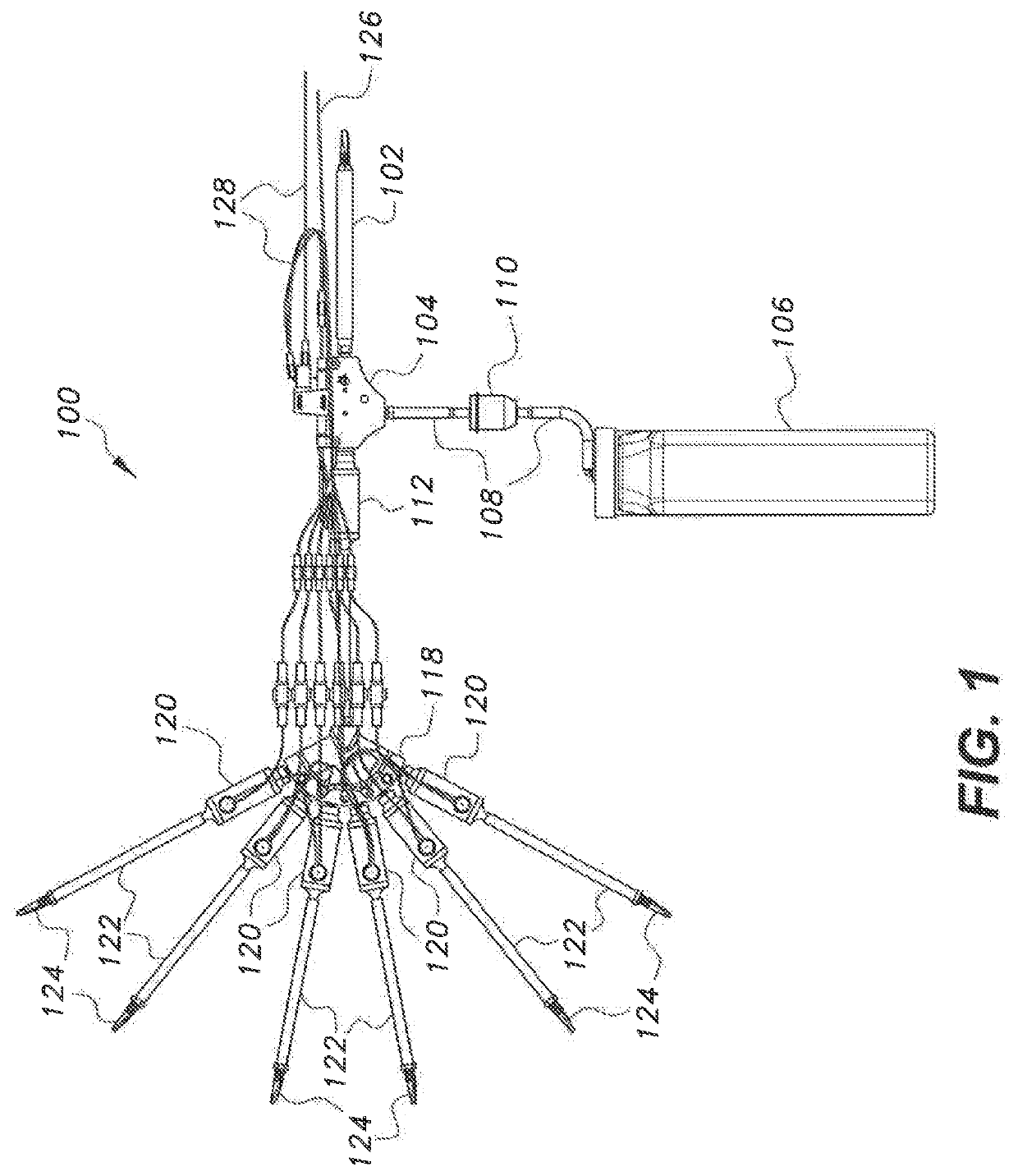
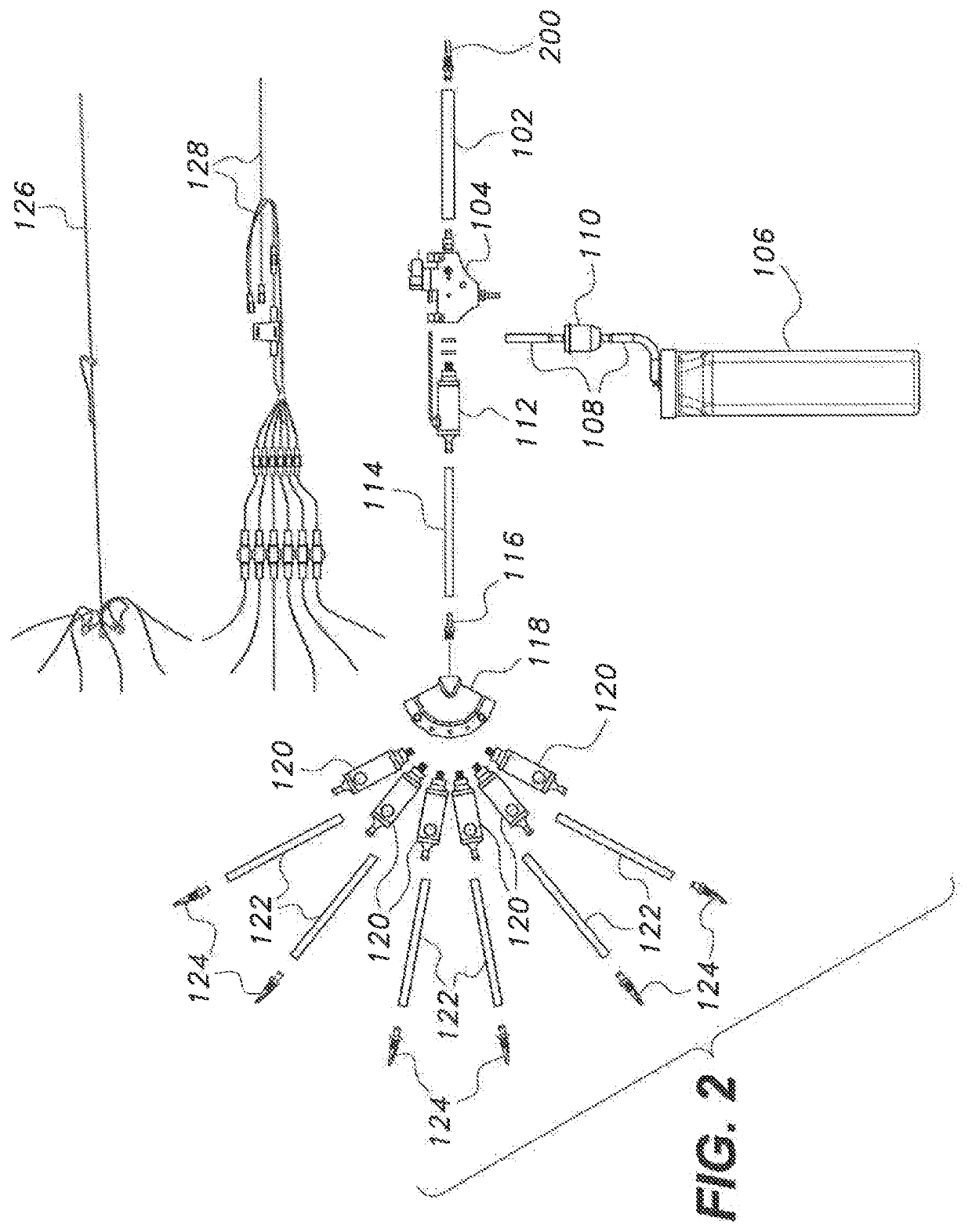
[0020]The hydrogen production system for internal combustion engines 100 is shown in FIGS. 1-2. The system 100 can be added to an air intake system of a vehicle's engine to enhance the combustion of the native fuel being used in the internal combustion engine (ICE). Typical native fuels used by ICEs are gasoline, natural gas, LP gas, compressed natural gas, methane gas, methanol, bio gas, and other vapor gas combinations. The system 100 is not intended to replace the vehicle's factory fuel system or the required use of standard fuel or alternate fuel for the vehicle. In addition, the system 100 does not attach to or require modification of the existing fuel system in the engine. The system relies on the existing electronic control module (ECM) or engine control unit (ECU), to regulate the air fuel ratio, and the consumption rate of the native fuel. When added to the engine's air intake system, the system 100 reduces emissions, increases fuel efficiency and actively avoids carbon bui...


PUM

PropertyMeasurementUnit
voltageaaaaaaaaaa
electrical currentaaaaaaaaaa
speedsaaaaaaaaaa

Abstract

The hydrogen production system for internal combustion engines includes an intake air scoop, a vacuum block having an air input port system for receiving air from the intake air scoop, a water reservoir connected to the vacuum block for providing water to be mixed with the air in the vacuum block, at least one primary generator assembly with an inlet port for receiving the air / water vapor mixture from the vacuum block and producing a mixture of hydrogen, produced oxygen, and fine hydrogen production vapor from a partially oxidized water fog, and a plurality of secondary hydrogen generator assemblies connected to the primary generator assembly for receiving this mixture. The engine vacuum draws this mixture into the intake manifold to provide an ideal fuel mixture for the engine.

Description

CROSS-REFERENCE TO RELATED APPLICATION[0001]This application claims the benefit of U.S. Provisional Patent Application No. 63 / 008,773, filed on Apr. 12, 2020.BACKGROUND1. Field[0002]The disclosure of the present patent application relates to internal combustion engines, and particularly to a hydrogen production system for internal combustion engines.2. Description of the Related Art[0003]In general, water and hydrogen injection systems for internal combustion engines are known. These systems pass an electrical current through water to produce hydrogen and oxygen (and other gasses) through electrolysis. The prior art systems, however, are inefficient in their use of electricity to produce the resultant gases. Some of the causes of these inefficiencies include poor water atomization, undersized electrodes, and short residence times in the electrolytic cell.[0004]Thus, a hydrogen production system for internal combustion engines solving the aforementioned problems is desired.SUMMARY[00...

Claims


Application Information

Patent Timeline
Patent Type & Authority Applications(United States)
IPC IPC(8): F02M25/025F02M35/104F02M35/10F02M25/022C25B1/042C25B9/17C25B15/08C25B9/65
CPCF02M25/025F02M35/104F02M35/10222F02M25/0222C25B9/65C25B1/042C25B9/17C25B15/08F02M35/10373C25B9/015C25B9/70C25B1/044C25B9/07C25B15/023C25B15/081F02M35/10209F02M35/10386F02M21/0206F02M21/0215
Inventor MILLER, DAVID D.
Owner MILLER DAVID D
Learn More