Downlink Channel Time Domain Position Determination Method and Device

a time domain and position determination technology, applied in the field ofwireless communications, can solve the problems of increasing the deployment cost of carriers, significant increase in the complexity of blindly detecting pdcch (epdcch), and no effective solution has been put forward

Active Publication Date: 2016-06-23
XIAN ZHONGXING NEW SOFTWARE
View PDF1 Cites 28 Cited by
  • Summary
  • Abstract
  • Description
  • Claims
  • Application Information

AI Technical Summary

Benefits of technology

[0091]The embodiment of the present invention provides a downlink channel time-domain position determination method and device, a terminal or a base station determines way for acquiring a time-domain position of a downlink control channel and / or a time-domain starting position of a downlink data channel corresponding to the downlink control channel according to the number of repetitions of resources corresponding to the downlink control channel and / or the downlink channel type, and then acquires the time-domain position of the downlink control channel and / or the time-domain starting position of the downlink data channel in accordance with the way. With the technical solution provided in the embodiment of the present invention, a coverage enhanced MTC terminal can be not subject to the PCFICH, and it still can determine the time-domain position of the downlink control channel as well as the time-domain starting position of the downlink data channel even without decoding the PCFICH channel in advance and correctly demodulate the downlink control and data channels, which achieves that the terminal correctly judges the time-domain position of the downlink channel, and solves the problem of the terminal correctly receiving the downlink data.

Problems solved by technology

In order to ensure that such type of MTC devices can maintain a normal communication with the base station system, usually it is required to deploy additional devices such as sites and relays and so on, which will undoubtedly greatly increase the deployment cost of the carriers.
But if the channel is removed directly and a corresponding avoidance policy is not given, the complexity of blindly detecting the PDCCH (ePDCCH) will be significantly increased.
With respect to the problem of PCFICH avoidance or function substitutions, currently no effective solutions have been put forward.

Method used


Image

  • Downlink Channel Time Domain Position Determination Method and Device
  • Downlink Channel Time Domain Position Determination Method and Device
  • Downlink Channel Time Domain Position Determination Method and Device

Examples


embodiment 1

[0105]First, in conjunction with the accompanying drawings, the present invention will be described.

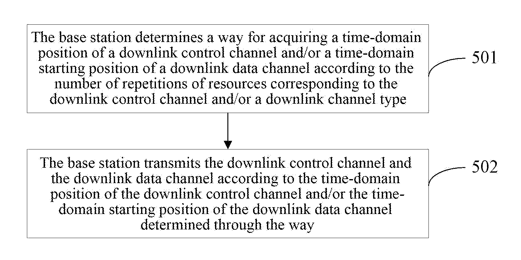
[0106]The embodiment of the present invention provides a downlink channel time-domain position determination method. First, at the network side, the base station is taken as an example to describe the flow of determining a time-domain position of a downlink channel. As shown in FIG. 5, the following steps are included:

[0107]in step 501, the base station determines a way for acquiring a time-domain position of a downlink control channel and / or a time-domain starting position of a downlink data channel according to the number of repetitions of resources corresponding to the downlink control channel and / or the downlink channel type;

[0108]the present step may include:

[0109]when the number of repetitions is 1, the base station determining the time-domain position of the downlink control channel and / or the time-domain starting position of the downlink data channel according to the PCFICH;

[0...

embodiment 2

[0150]In the following, in conjunction with the accompanying drawings, the present invention will be described.

[0151]The embodiment of the present invention provides a downlink channel time-domain position determination method, and in the following, the flow of using this method to determine the time-domain position of the downlink control channel or the time-domain starting position of the data channel through the signaling indication in the Frequency Division Duplexing (FDD) system will be described. The signaling indication in the embodiment of the present invention is borne in the MIB.

[0152]That is, the control and data of the same terminal are transmitted in the same subframe, that is, the common intra-frame scheduling. Moreover, the number of symbols occupied by the control channels in a plurality of subframes where the control information is repeated is the same. For example, the subframe structures of the downlink subframe control and data channels are as shown in FIG. 7, th...

embodiment 3

[0160]In the following, in conjunction with the accompanying drawings, the present invention will be described.

[0161]The embodiment of the present invention provides a downlink channel time-domain position determination method, still the way for determining the time-domain positions of the downlink control channel and the downlink data channel by means of signaling will be described, and the signaling is borne in the SIB of the blindly-detected public messages to be transmitted. Meanwhile, the downlink control channel and the downlink data channel of the same terminal are still transmitted in the same subframe, and the information of the downlink control channel only contains the user-specific control information.

[0162]At this point, transmission information of some public messages such as the SIB, paging and RAR does not require the PDCCH signaling to indicate the frequency domain position of the subframe, but it is directly transmitted to the user equipment through the PDSCH.

[0163...


PUM


Abstract

A downlink control channel time-domain position determination method and device are disclosed. The method includes: a terminal determining a way for acquiring a time-domain position of a downlink control channel and/or a time-domain starting position of a downlink data channel corresponding to the downlink control channel according to a number of repetitions of resources corresponding to the downlink control channel and/or a downlink channel type; the terminal obtaining the time-domain position of the downlink control channel and/or the time-domain starting position of the downlink data channel in accordance with the way.

Description

CROSS-REFERENCE TO RELATED APPLICATION(S)[0001]This application is the U.S. National Phase application of PCT application number PCT / CN2014 / 080083 having a PCT filing date of Jun. 17, 2014, which claims priority of Chinese patent application 201310337474.0 filed on Aug. 5, 2013, the disclosures of which are hereby incorporated by reference.TECHNICAL FIELD[0002]The present invention relates to the field of wireless communications, and more particularly, to a downlink channel time-domain position determination method and device.BACKGROUND OF RELATED ART[0003]The MTC User Equipment (MTC UE) is also known as an M2M user communication device and is the main application form of the Internet of things at this stage. Smart metering is one of the most typical applications of the MTC device, and most of smart metering type MTC devices are all fixedly installed in environments with low coverage performance such as a basement and so on. In order to ensure that such type of MTC devices can maint...

Claims


Application Information

Patent Timeline
Patent Type & Authority Applications(United States)
IPC IPC(8): H04L5/00H04L5/14H04W72/04
CPCH04L5/0092H04L5/1469H04W72/0446H04L5/008
Inventor LI, XINCAIDAI, BOXIA, SHUQIANGSHI, JINGLIU, KUNFANG, HUIYING
Owner XIAN ZHONGXING NEW SOFTWARE
Why Eureka
Try Eureka