
Light fixture with multiple dimming capabilities

a technology of light fixtures and dimming capabilities, applied in the direction of electric variable regulation, process and machine control, instruments, etc., can solve the problems of inability to achieve the dimming range of light emitting diodes (leds), which are being used in place of incandescent lights, and the operating cost reduction, so as to achieve the dimming range significantly smaller and the power/voltage variation is not the same as incandescent lights

Active Publication Date: 2016-06-23
CHAUVET & SONS LLC
View PDF3 Cites 2 Cited by
  • Summary
  • Abstract
  • Description
  • Claims
  • Application Information

AI Technical Summary

Benefits of technology

The present invention is a device, system, and method that can automatically sensing dimming signals from power / voltage dimmers and data controllers, and prioritize between them to determine which dimming signal to apply. This invention allows for more efficient and effective dimming control in various light fixtures and scenarios. It has been designed to address existing problems in the art and provides a solution that is efficient and effective in controlling the brightness of lighting. The device is flexible and can be used in different light fixtures and scenarios. Overall, the invention improves the precision and control of dimming in lighting systems.

Problems solved by technology

However, dimming of light emitting diodes (LEDs), which are being used in place of incandescent lights in many applications due to their greater efficiency and decreased operating costs, as well as some other light technologies, cannot be accomplished by varying the power / voltage in the same manner as incandescent lights.
Because LEDs operate at significantly lower powers / voltages than incandescent lights, conventional dimmers (i.e., “triac dimmers” or “legacy dimmers”) designed for incandescent lights do not function properly with LEDs, resulting in a significantly smaller dimming range.
The inability of LED light fixtures to function properly with these legacy power dimming systems has been an impediment to the adoption of LED light fixtures in these existing facilities that have already invested significant resources to build the current infrastructure.
These facilities and installations using incandescent lights and legacy power dimmers cannot simply add dimmable LED fixtures into the existing power infrastructure without also making substantial infrastructure changes to power the LED fixtures, because the LED fixtures will not operate properly, as the power in the existing infrastructure is varied to dim the incandescent lights co-existing in the system.
It also results in facilities with incandescent lights not having access to advanced lighting fixtures, features and technologies that are only offered with LEDs.

Method used


Image

  • Light fixture with multiple dimming capabilities
  • Light fixture with multiple dimming capabilities
  • Light fixture with multiple dimming capabilities

Examples


Embodiment Construction

[0018]Before explaining the disclosed embodiment of the present invention in detail, it is to be understood that the invention is not limited in its application only to the details of the particular arrangement shown since the invention is capable of other embodiments. Also, the terminology used herein is for the purpose of description and not of limitation.

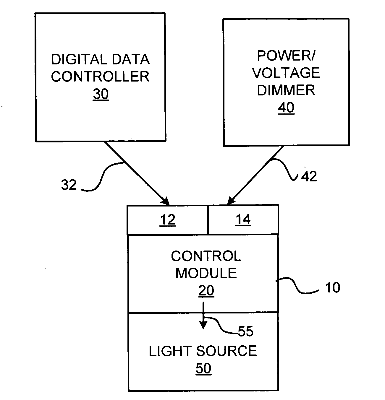
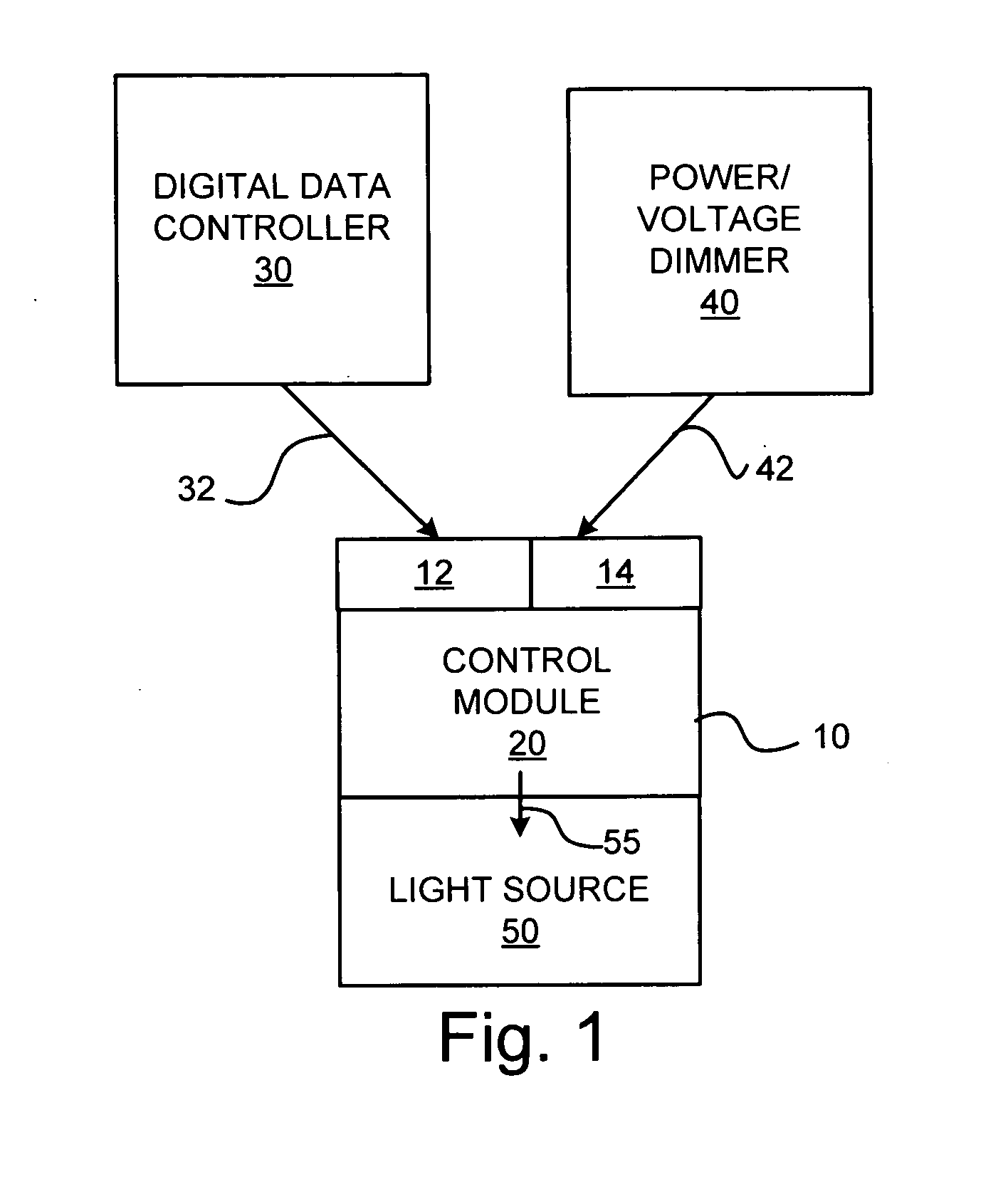
[0019]Referring now to FIG. 1, a light fixture 10 is provided that is capable of varying the light intensity output by the light fixture 10, in response to dimming control signals received from one or more traditional (i.e., legacy) incandescent light voltage variation dimmer switches 40 and one or more digital data controllers 30. The incandescent light voltage variation dimmer switch 40 is hereinafter referred to as the power dimmer or legacy dimmer 40, and the dimming signal received from the power dimmer 40 is hereinafter referred to as the power dimming signal 42.

[0020]The digital data controller 30 provides digital data con...


PUM


Abstract

A light fixture with multiple dimming capabilities is provided. More particularly, a device, system and method are provided for automatically sensing the presence of dimming signals from one or more power / voltage dimmers (i.e., phase-cut dimmers) and one or more data controllers providing dimming control signals according to a digital data controller protocol, and determining a priority between the two, for applying a dimming signal.

Description

CROSS-REFERENCE TO RELATED APPLICATIONS[0001]The present application claims benefit of co-pending Provisional Patent Application No. 62 / 096,063, filed on Dec. 23, 2014; that application being incorporated herein, by reference, in its entirety.BACKGROUND OF THE INVENTION[0002]1. Field of the Invention[0003]The present invention relates to a light fixture and, more particularly, to a light fixture capable of selectively varying the light intensity in response to variations in power and / or data.[0004]2. Description of the Related Art:[0005]The use of dimmers to vary the intensity of light is common in light fixtures used in homes and commercial facilities and for other applications, such as stage lighting. Dimming of incandescent lights is typically accomplished by varying the power / voltage delivered to the lamp, through a process known as “phase-cut” or rheostat dimming, by sliding a switch or turning a knob. However, dimming of light emitting diodes (LEDs), which are being used in pl...

Claims


Application Information

Patent Timeline
Patent Type & Authority Applications(United States)
IPC IPC(8): H05B33/08H05B37/02H05B44/00
CPCH05B33/0845H05B37/0272H05B37/0209H05B47/19
Inventor SELLERS, FORD HUNTERGRAHAM, MICHAEL
Owner CHAUVET & SONS LLC
Features
  • Generate Ideas
  • Intellectual Property
  • Life Sciences
  • Materials
  • Tech Scout
  • Unparalleled Data Quality
  • Higher Quality Content
  • 60% Fewer Hallucinations
Learn More