Agricultural Harvester Unloading Via Header Structure

a header structure and harvester technology, applied in the field of agricultural harvesters, can solve the problems of increasing the difficulty of discharging or unloading of the on-board tank or container, increasing the overall weight of the agricultural, and imposing large forces on the harvester frame and the upper structure of the on-board tank, so as to achieve the effect of reducing the disadvantages

Active Publication Date: 2016-06-30
CNH BELGIUM +1
View PDF5 Cites 2 Cited by
  • Summary
  • Abstract
  • Description
  • Claims
  • Application Information

AI Technical Summary

Benefits of technology

[0013]In accordance with the present invention, an agricultural harvester is provided that enables an alternative unloading of the harvested crop from the on-board tank, compared to a conventional discharging whereby a comparatively long discharge tube is used, the discharge tube being mounted to an on-board tank of the agricultural harvester and extending as far as the width of the header.
[0019]In the present invention, the harvested crop is thus brought towards an end of the header where it is picked up by a discharger. Compared to the conventional approach, a much lighter discharger or discharge structure can be applied. Further, compared to the conventional discharging, the unloading as provided by the present invention may result in less damage to the harvested crop, due to a more ‘gentle’ conveying. In this respect, it can be noted that, in order to discharge the harvested crop in the conventional manner, a substantially vertically positioned auger is typically applied to transport the harvested crop upwards, towards the discharging tube. Such an arrangement has a comparatively high power demand and exerts an important strain on the harvested crop. In the present invention, the harvested crop is transported towards a distal end of the header, e.g. using a conveyer belt. Such transport is found to be less power consuming compared to the conventional approach where typically a vertically oriented auger is used, and enables a more rapid and smooth transport of the harvested crop.
[0020]Further, it is worth mentioning that the unloading procedure as can be performed using an agricultural harvester according to the invention can be more easily observed and checked by the operator of the agricultural harvester, since the unloading is substantially performed via the front side of the harvester.
[0021]In an embodiment, the discharger of the agricultural harvester comprises a discharge tube that is pivotally mounted at or near the distal end of the header. This enables the overall width of the transporter / discharger combination to be reduced during transport or when no discharging is performed. Such discharger can, in an embodiment, be mounted to the transporter or the header.

Problems solved by technology

Due to an ever increasing width of the applied header structures of agricultural harvesters, the discharging or unloading of the on-board tank or container becomes more and more difficult.
Due to the weight and the large extension of the weight beyond the central axis of the harvester, there is a high load on one side of the harvester that may result in a side tilt of the harvester which may cause extensive forces on the harvester frame and on-board tank upper structure.
The increasing weight of the discharge tube also adds to the overall weight of the agricultural harvester and may thus affect the impact on the soil, in particular provide in an increased pressure on the soil.

Method used


Image

  • Agricultural Harvester Unloading Via Header Structure
  • Agricultural Harvester Unloading Via Header Structure
  • Agricultural Harvester Unloading Via Header Structure

Examples


Embodiment Construction

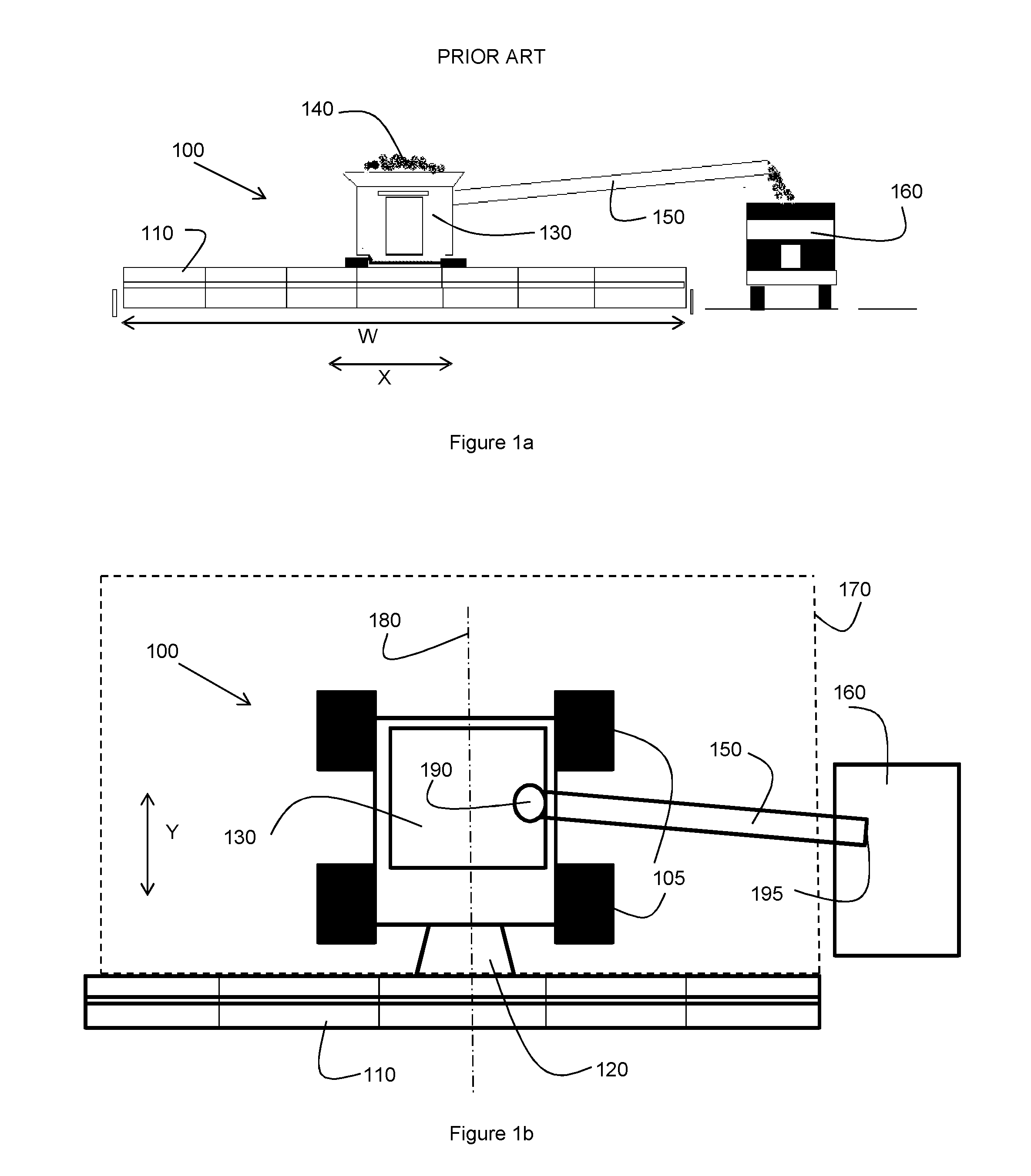
[0043]FIGS. 1a and 1b schematically depict a front view and a top view of an agricultural harvester as known in the art.

[0044]As schematically shown in FIGS. 1a and 1b, the agricultural harvester 100 as known in the art comprises a header 110 extending in a transverse direction (indicated as the x-direction), arranged to harvest the crop such as corn or grain and supply the harvested crop via a so-called feeder 120 to an on-board tank 130 of the harvester 100. The harvester 100 as shown further comprises a set of wheels 105. During operation, the harvester moves in the longitudinal direction (indicated as the Y-direction), whereby the harvested crop 140 is gathered in the on-board tank 130. For efficiency purposes, the on board tank 130 is emptied or unloaded at regular instances ‘on the go’, such that the harvesting process need not be interrupted. In known harvesters, use is made of a discharge tube 150 for such on the go discharging of the on-board tank into a truck or trailer 15...


PUM


Abstract

An agricultural harvester has a header for harvesting a crop, an on-board container for storing the harvested crop, and a feeder adapted to receive the harvested crop from the header and provide the harvested crop to the on-board container. The agricultural harvester further has a transporter adapted to transport the harvested crop from the on-board container towards a distal end of the header; at least part of the transporter being mounted to the header or the feeder and a discharger in communication with the transporter and adapted to receive the harvester crop as transported by the transporter, at or near the distal end of the header, the discharger having a discharge outlet for discharging the harvested crop.

Description

[0001]This application is the US National Stage filing of International Application Serial No. PCT / EP2014 / 067285 filed on Aug. 13, 2014 which claims priority to Belgian Application BE2013 / 0540 filed Aug. 13, 2013, each of which is incorporated herein by reference in its entirety.FIELD OF THE INVENTION[0002]The invention relates to the field of agricultural harvesters such as combine harvesters, and more specifically to the unloading of such harvesters.BACKGROUND OF THE INVENTION[0003]The present invention relates to the field of agricultural harvesters, as e.g. applied for the harvesting of a crop such as grain or corn. Typically, such a harvester is equipped with a header or header structure for cutting the crop and providing the cut or harvested crop, e.g. via a feeder or feeding structure to an on-board storage tank or container. Typically, the header or header structure has an elongated structure that may span up to 50 or 70 feet and comprises a cutting member such as a cutter b...

Claims


Application Information

Patent Timeline
Patent Type & Authority Applications(United States)
IPC IPC(8): A01D90/10A01D61/00A01D75/18
CPCA01D90/10A01D2101/00A01D61/002A01D75/182A01D41/1217
Inventor MISSOTTEN, BART M.A.
Owner CNH BELGIUM
Why Eureka
Try Eureka