Piezoelectric actuator, liquid discharging apparatus and method for producing piezoelectric actuator

a technology of liquid discharging apparatus and actuator, which is applied in the direction of piezoelectric/electrostrictive/magnetostrictive devices, printing, electrical transducers, etc., can solve the problems of reducing the deformation efficiency, and achieve the effect of reducing the voltage drop and being easy to arrang

Active Publication Date: 2016-06-30
BROTHER KOGYO KK
View PDF1 Cites 3 Cited by
  • Summary
  • Abstract
  • Description
  • Claims
  • Application Information

AI Technical Summary

Benefits of technology

[0019]In the present teaching, the plurality of piezoelectric elements are arranged in the first direction to construct the two piezoelectric element rows (first and second piezoelectric element rows) arranged side by side in the second direction. Further, the drive wires included in the plurality of drive wires and corresponding to the piezoelectric elements included in the plurality of piezoelectric elements and constructing the second piezoelectric element row are each extended in the second direction while passing between two adjacent piezoelectric elements among the piezoelectric elements constructing the first piezoelectric element row, reaching up to the contact section. Here, in the second piezoelectric element row included in the two piezoelectric element rows and located on the side opposite to the contact section relative to the first piezoelectric element row, the distance from the piezoelectric elements to the contact section is greater than in the first piezoelectric element row; and this makes the voltage drop, occurring when the electric current flows from the second electrode of each of the piezoelectric elements constructing the second piezoelectric element row to the contact section, be great. In view of this, the present teaching provides the conductive wires in the second piezoelectric element row located to be far from the contact section; each of the con...

Problems solved by technology

However, increasing the thickness of the common electrode involves such a problem that the deformation ...

Method used


Image

  • Piezoelectric actuator, liquid discharging apparatus and method for producing piezoelectric actuator
  • Piezoelectric actuator, liquid discharging apparatus and method for producing piezoelectric actuator
  • Piezoelectric actuator, liquid discharging apparatus and method for producing piezoelectric actuator

Examples


Embodiment Construction

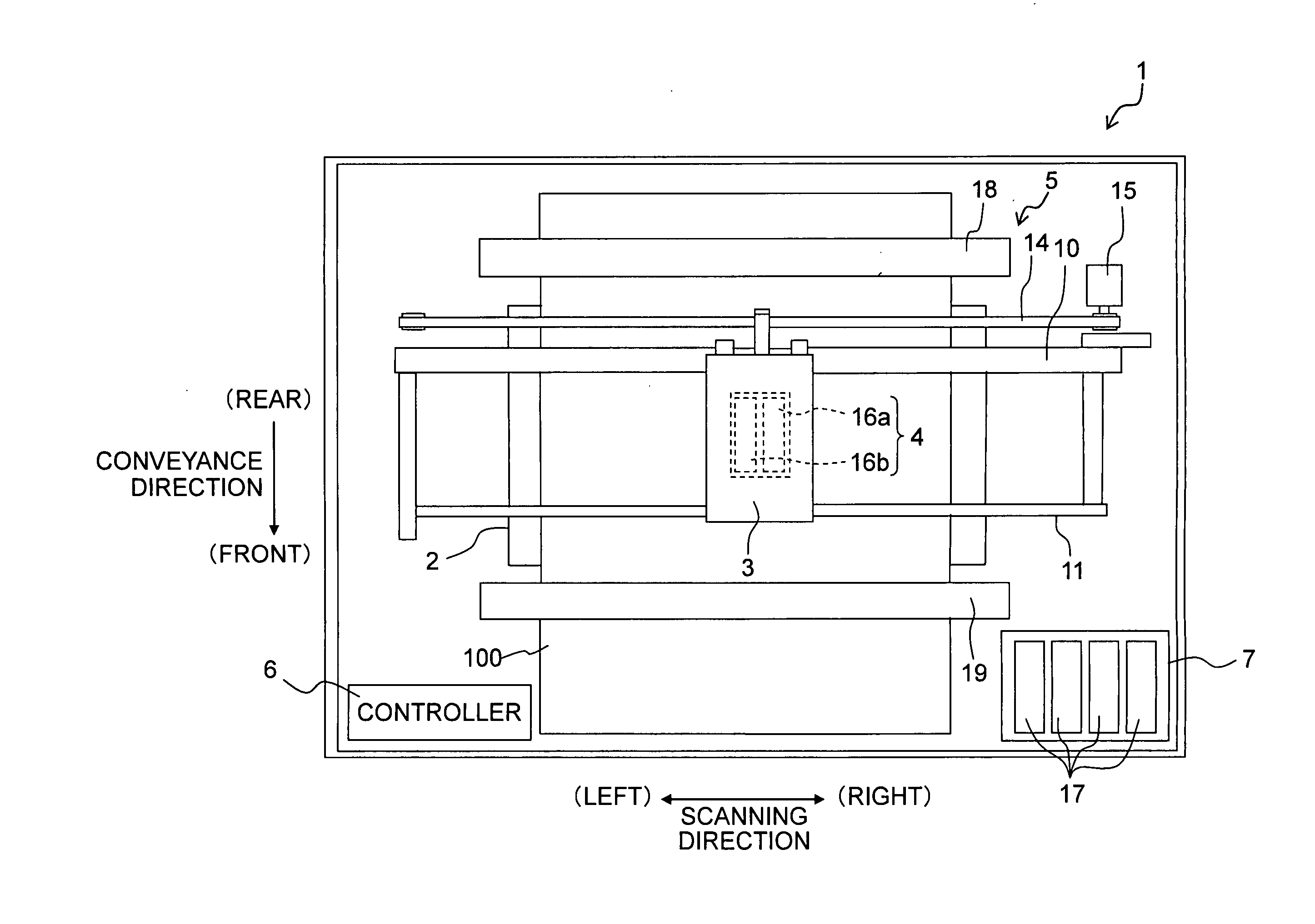
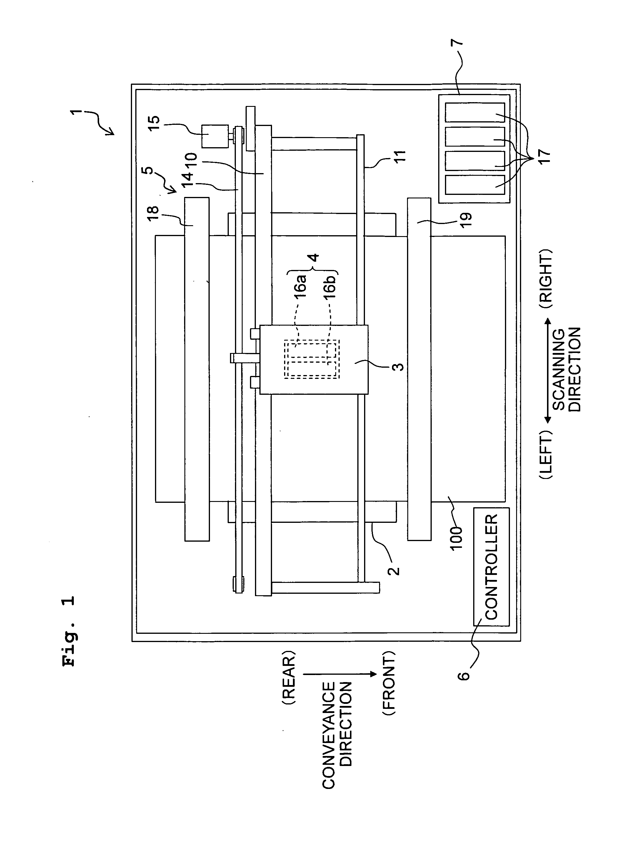
[0033]Next, an embodiment of the present teaching will be described, with reference to the drawings as appropriate. FIG. 1 is a schematic plane view of a printer according to this embodiment. At first, the overall configuration of an ink-jet printer 1 will be explained with reference to FIG. 1. Note that a “scanning direction” as depicted in FIG. 1 is defined as the left-right direction of the printer 1. Further, the upstream side and the downstream side in a “conveyance direction” as depicted in FIG. 1 are defined as the rear (back) side and the front (forward) side, respectively, of the printer 1. Furthermore, a direction orthogonal to the scanning direction and the conveyance direction (direction perpendicular to the sheet surface of FIG. 1) is defined as the up-down direction of the printer 1. Note that the front side of the sheet surface of FIG. 1 is upward, and the other side of the sheet surface of FIG. 1 is downward.

[0034]

[0035]As depicted in FIG. 1, the ink-jet printer 1 is...


PUM


Abstract

There is provided a piezoelectric actuator including: a plurality of piezoelectric elements forming first and second piezoelectric element rows, and including first, second electrodes and piezoelectric portion; an electrode conductive portion; a contact section; a plurality of drive wires,; and conductive wires. A part of the drive wires corresponding to the piezoelectric elements of the second piezoelectric element row are extended toward the contact section while passing between two adjacent piezoelectric elements of the first piezoelectric element row which are adjacent in the first direction. The conductive wires are arranged between two adjacent piezoelectric elements of the second piezoelectric element row, each of the conductive wires is conducted, at two locations thereof apart in the second direction, with the electrode conductive portion.

Description

CROSS REFERENCE TO RELATED APPLICATION[0001]The present application claims priority from Japanese Patent Application No. 2014-265265 filed on Dec. 26, 2014 the disclosure of which is incorporated herein by reference in its entirety.BACKGROUND[0002]1. Field of the Invention[0003]The present invention relates to a piezoelectric actuator and a liquid discharging apparatus provided with the piezoelectric actuator.[0004]2. Background Art[0005]There is known an ink-jet head as a liquid discharging apparatus. The ink-jet head is provided with a head body formed with a plurality of nozzles and a plurality of pressure chambers communicating with the plurality of nozzles, respectively; and an actuator including a plurality of piezoelectric elements corresponding to the plurality of pressure chambers, respectively.[0006]The plurality of pressure chambers in the head body are arranged corresponding to the plurality of nozzles, respectively, and construct four pressure chamber rows arranged side...

Claims


Application Information

Patent Timeline
IPC IPC(8): B41J2/14B41J2/16
CPCB41J2/1631B41J2/14201B41J2/04501B41J2/14233B41J2/161B41J2/1628B41J2/1629B41J2/1643B41J2/1646B41J2002/14266B41J2002/14459B41J2002/14491
Inventor KAKIUCHI, TORUHAYASHI, HIDEKIHIRAI, KEITAHIROTA, ATSUSHI
Owner BROTHER KOGYO KK
Why Eureka
Try Eureka