Optical Unit and Display Apparatus

a technology of optical units and display devices, applied in lighting and heating devices, planar/plate-like light guides, instruments, etc., can solve problems such as inability to cope with user abnormal sensations

Inactive Publication Date: 2016-06-30
SAKAI DISPLAY PROD
View PDF2 Cites 0 Cited by
  • Summary
  • Abstract
  • Description
  • Claims
  • Application Information

AI Technical Summary

Benefits of technology

[0011]In consideration of the above-mentioned circumstances, it is an object of the present invention to provide an optical unit which includes a light guide plate configured to emit light made incident thereon through a light incident side surface from one surface thereof, and a reflection sheet disposed opposite to the light guide plate, wherein the reflection sheet has a projection piece protruding on one edge thereof perpendicular to a surface of the reflection sheet, and the projection piece is held by any one side surface of the light guide plate with being in surface contact therewith, such that it is possible to solve the above-described problem that the light guide plate may not be provided by extending the same due to the hanging mechanism being disturbed, and extend the image display region, as well as the complex hanging mechanism as described above is unnecessary, such that luminance unevenness does not occur at a portion of the image display region corresponding to the hanging mechanism, and a display apparatus including the same.

Problems solved by technology

Therefore, in the display apparatus having such a structure, the hanging mechanism is to be an obstacle, such that it is difficult to provide the light guide plate by extending the same to a position of the hanging mechanism.
In addition, when an image display region extends so that a position relating to the hanging mechanism is included in the image display region in an image display screen, while the light guide plate does not extend to the position of the hanging mechanism, a problem (luminance unevenness) occurs at a portion corresponding to the hanging mechanism in the image display region due to the presence of the hanging mechanism, and thereby provides an abnormal feeling to a user.
However, the liquid crystal display apparatus of Japanese Patent Laid-open Publication No. 2002-311430 does not have the structure for suspending the light guide plate or the reflection sheet, and ingenuity regarding the above-described problem has not been conducted, such that it is not possible to cope therewith.

Method used


Image

  • Optical Unit and Display Apparatus
  • Optical Unit and Display Apparatus
  • Optical Unit and Display Apparatus

Examples


embodiment 1

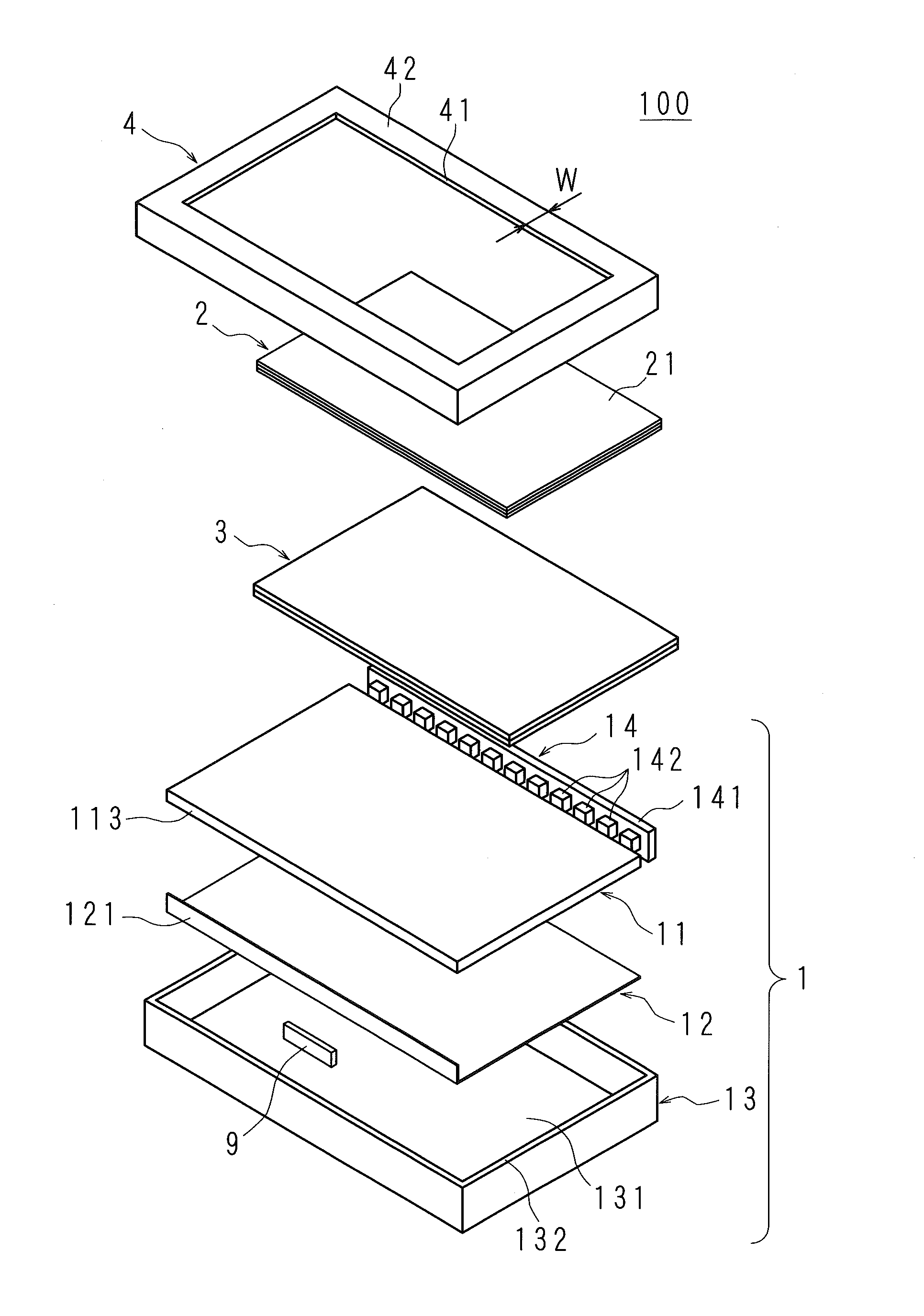
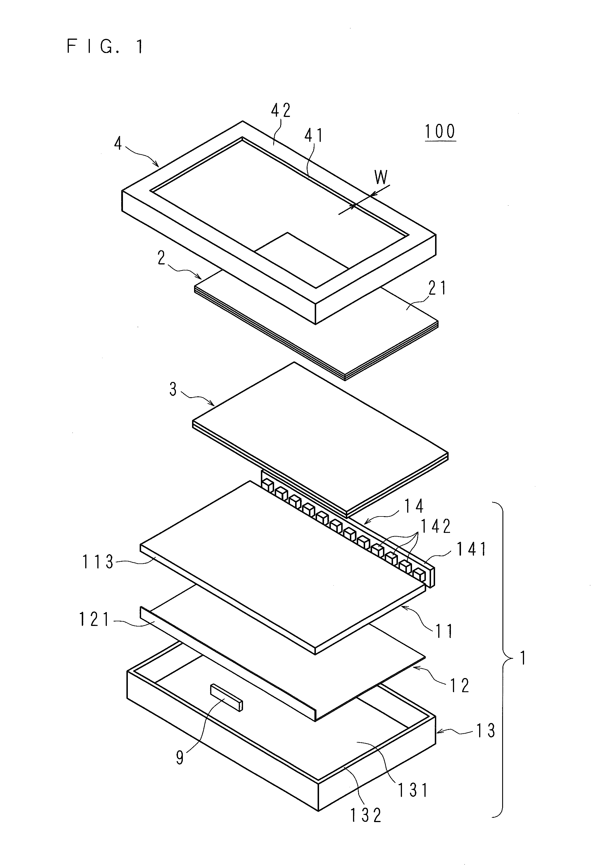
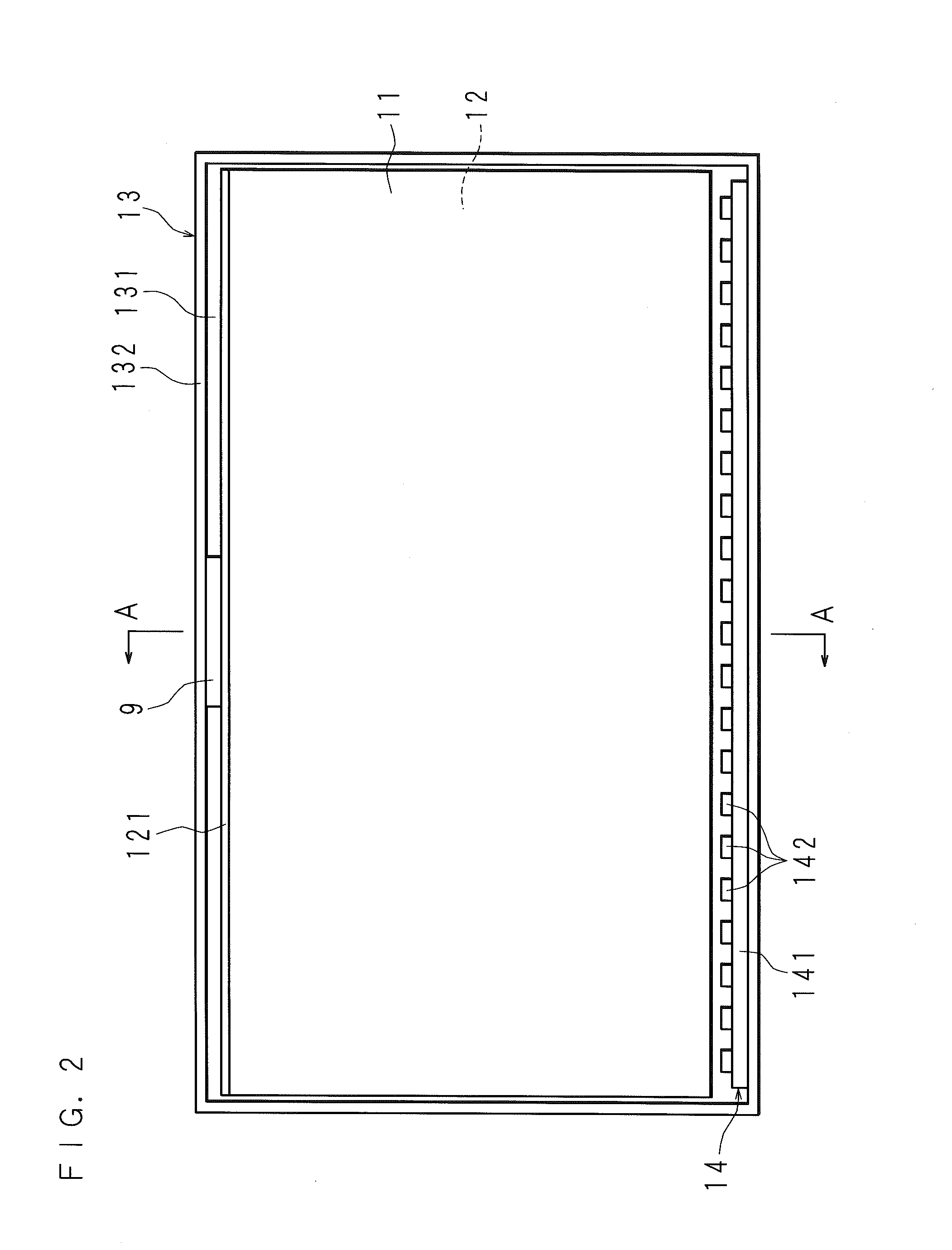
[0031]FIG. 1 is an exploded perspective view illustrating a configuration of main components of a liquid crystal television according to Embodiment 1 of the present invention, FIG. 2 is a view schematically illustrating a state in which a light guide plate and a reflection sheet are stored in the liquid crystal television according to Embodiment 1 of the present invention, and FIG. 3 is a longitudinal-sectional view taken along line A-A in FIG. 2. In the drawings, a liquid crystal television 100 according to the embodiments of the present invention is illustrated.

[0032]The liquid crystal television 100 includes a light source device 1, a liquid crystal display panel 2, an optical sheet 3 and a front chassis 4 in which the liquid crystal display panel 2 and the optical sheet 3 are stored and the like.

[0033]Further, the light source device 1 includes a light source unit 14, a light guide plate 11 which guides light made incident thereon from the light source unit 14 to one surface the...

embodiment 2

[0065]In Embodiment 1, the case in which the projection piece 121 has a strip shape and protrudes perpendicular to the one surface of the reflection sheet 12, and the projection piece 121 has a longitudinal dimension substantially the same as the dimension of the one long-side edge of the reflection sheet 12 and a lateral dimension substantially the same as the thickness of the light guide plate 11 has been described as an example, but the present invention is not limited thereto.

[0066]FIG. 4 is a view describing a relation between the light guide plate 11, the reflection sheet 12 and the light source unit 14, in a liquid crystal television 100 according to Embodiment 2 of the present invention, and FIG. 5 is a view schematically illustrating a state in which the light guide plate 11 and the reflection sheet 12 are stored in the liquid crystal television 100 according to Embodiment 2 of the present invention.

[0067]In the liquid crystal television 100 according to Embodiment 2 of the...

embodiment 3

[0076]In Embodiment 1, the case in which the projection piece 121 has a strip shape and protrudes perpendicular to the one surface of the reflection sheet 12, and the projection piece 121 has a longitudinal dimension substantially the same as the dimension of the one long-side edge of the reflection sheet 12 and a lateral dimension substantially the same as the thickness of the light guide plate 11 has been described as an example, but the present invention is not limited thereto.

[0077]FIG. 6 is a view describing a relation between the light guide plate 11, the reflection sheet 12 and the light source unit 14, in a liquid crystal television 100 according to Embodiment 3 of the present invention, and FIG. 7 is a view schematically illustrating a state in which the light guide plate 11 and the reflection sheet 12 are stored in the liquid crystal television 100 according to Embodiment 3 of the present invention.

[0078]In the liquid crystal television 100 according to Embodiment 3 of the...


PUM


Abstract

Provided is an optical unit which includes a light guide plate configured to emit light made incident thereon through a light incident side surface from one surface thereof, and a reflection sheet disposed to face the light guide plate, wherein the reflection sheet has a projection piece which protrudes with respect to a surface of the reflection sheet on one edge thereof. The projection piece is held with being in surface contact with any one side surface of the light guide plate, thereby the reflection sheet is held so as to face the light guide plate.

Description

[0001]This application is the national phase under 35 U.S.C. §371 of PCT International Application No. PCT / JP2013 / 070375 which has an International filing date of Jul. 26, 2013 and designated the United States of America.BACKGROUND[0002]1. Technical Field[0003]The present invention relates to an optical unit which includes a light guide plate for emitting light made incident on a side surface from one surface thereof, and a reflection sheet disposed opposite to the light guide plate, and a display apparatus including the optical unit.[0004]2. Description of Related Art[0005]Recently, a display apparatus such as a liquid crystal television has been widely distributed. Such a display apparatus includes a light guide plate and a reflection sheet disposed opposite to the light guide plate.[0006]For example, Japanese Patent Laid-open Publication No. 2002-311430 discloses a liquid crystal display apparatus including a diffusion sheet, a lens sheet, and a diffusion sheet which are disposed...

Claims


Application Information

Patent Timeline
Patent Type & Authority Applications(United States)
IPC IPC(8): F21V8/00
CPCG02B6/0088G02B6/0093G02B6/0033
Inventor KUROMIZU, YASUMORI
Owner SAKAI DISPLAY PROD
Why Eureka
Try Eureka