
Control of power consumption

a technology of power consumption and control, applied in the direction of computer control, process and machine control, instruments, etc., can solve the problems of large energy consumption of facility housing such systems, large power consumption of computing configurations and systems,

Active Publication Date: 2016-06-30
TAHOE RES LTD
View PDF7 Cites 41 Cited by
  • Summary
  • Abstract
  • Description
  • Claims
  • Application Information

AI Technical Summary

Benefits of technology

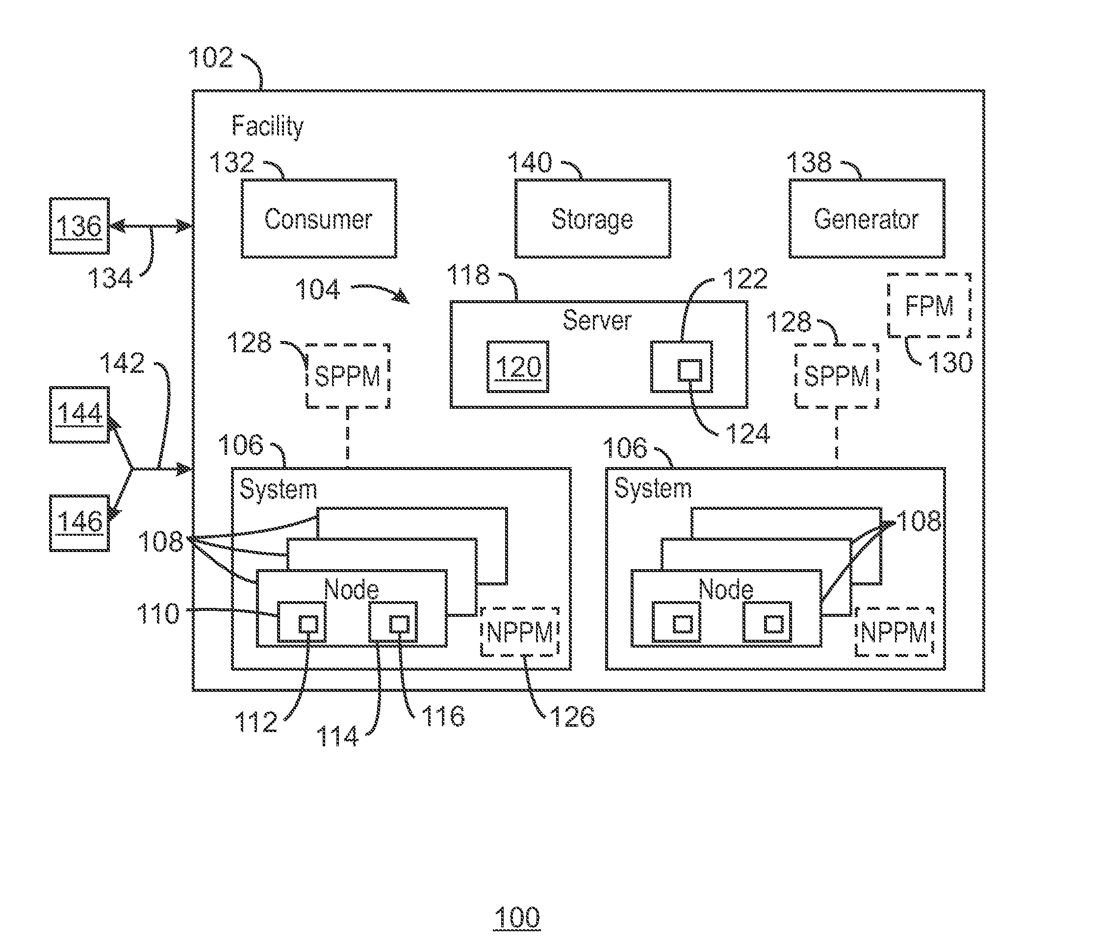
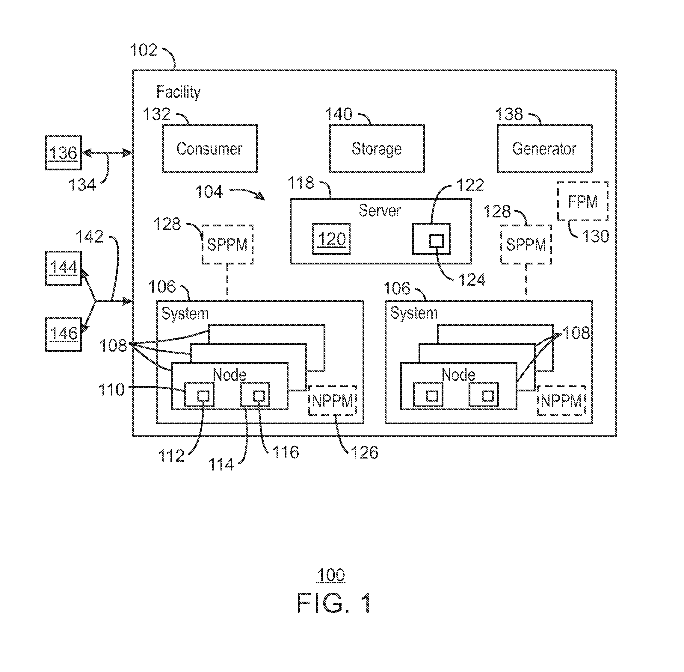
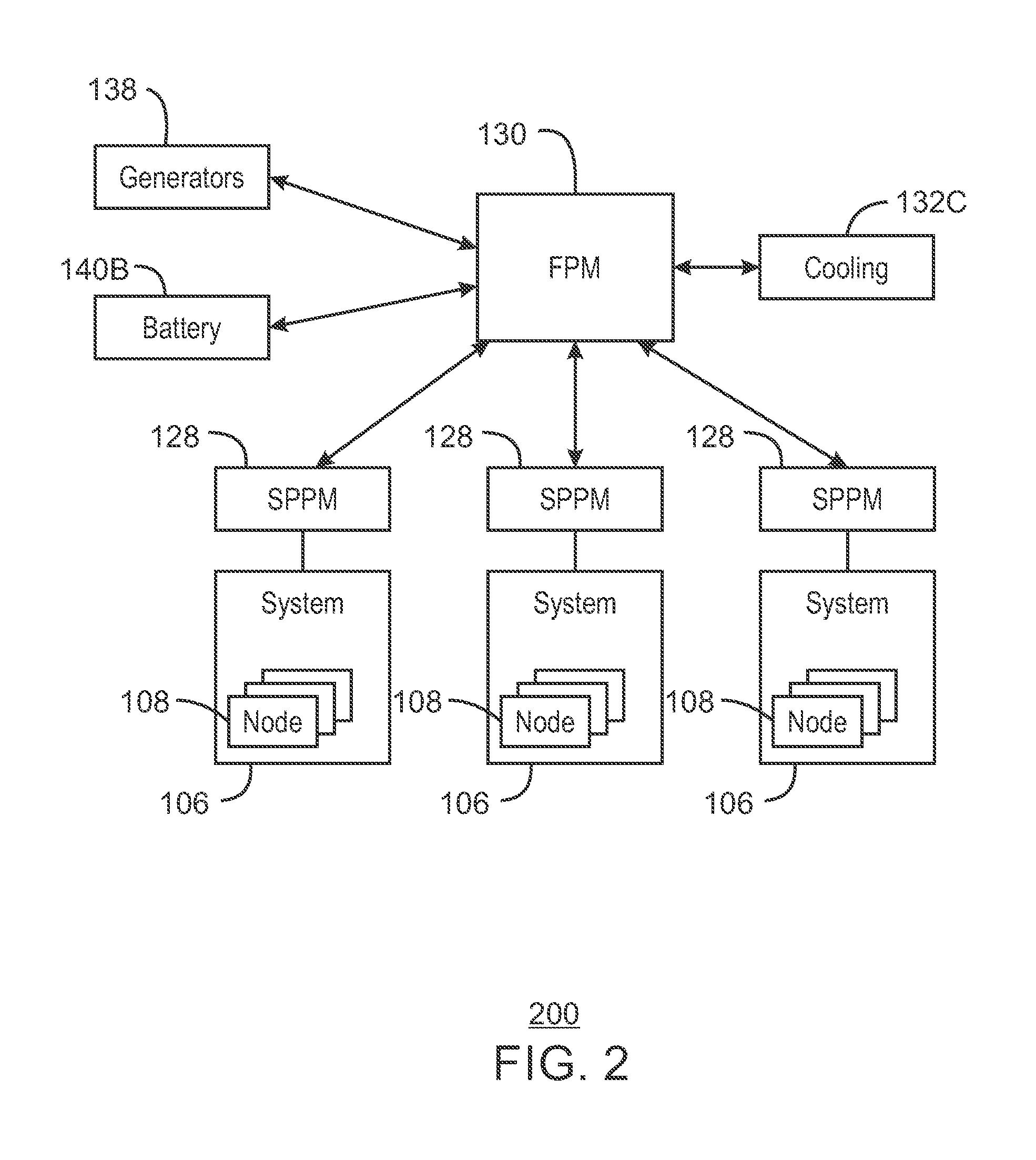
The present techniques relate to managing power consumption in a facility housing multiple compute nodes for distributed computing. The goal is to control power consumption within a specific range or band, rather than just reducing overall power usage. This is important for several reasons, including the need to meet the requirements of a utility provider and the need to ensure consistent and reliable service. The techniques also address issues of power allocation and variations in power consumption. The patent text describes a facility with a system level and node level power management system, as well as a power manager hierarchy and actions. The patent also includes a diagrammatical representation of the facility and a computer-readable medium for power management. The technical effects of the techniques include improved consistency of service and efficiency of power utilization.

Problems solved by technology

A variety of computing configurations and systems may consume relatively large amounts of power.
The facility housing such systems can require significant energy.
Unfortunately, again, systems such as distributed systems, HPC systems, and others, which may have hundreds or thousands of processors, servers, or compute nodes performing tasks, typically consume significant power.
Such may be especially problematic in the “Big Data” era.
Further, variations in power consumption and issues of power allocation may also be problematic.

Method used


Image

  • Control of power consumption
  • Control of power consumption
  • Control of power consumption

Examples


example 2

[0072 incorporates the subject matter of Example 1. In this example, to adjust power consumption, via the power balloon, controls rate of the power consumption.

example 3

[0073 incorporates the subject matter of any combination of Examples 1-2. In this example, the computing comprises distributed computing and the job comprises a distributed computing job. Further, to manage power consumption includes managing power consumption at a facility level, a system level, and a node level, and wherein the power band comprises a range from a minimum power consumption to a maximum power consumption.

example 4

[0074 incorporates the subject matter of any combination of Examples 1-3. In this example, the power balloon is a node power balloon.


PUM


Abstract

A system and method for computing at a facility having systems of multiple compute nodes to execute jobs of computing. Power consumption of the facility is managed to within a power band. The power consumption may be adjusted by implementing (e.g., by a power balloon) activities having little or no computational output.

Description

CROSS-REFERENCE TO RELATED APPLICATIONS[0001]The present application is related to the U.S. patent application Ser. No. ______ (Attorney Docket No. 42P73498) entitled ______ filed ______; the U.S. patent application Ser. No. ______ (Attorney Docket No. 42P74562) entitled ______ filed ______; the U.S. patent application Ser. No. ______ (Attorney Docket No. 42P74566) entitled ______ filed ______; the U.S. patent application Ser. No. ______ (Attorney Docket No. 42P74567) entitled ______ filed ______; the U.S. patent application Ser. No. ______ (Attorney Docket No. 42P74568) entitled ______ filed ______; the U.S. patent application Ser. No. ______ (Attorney Docket No. 42P74569) entitled ______ filed ______; the U.S. patent application Ser. No. ______ (Attorney Docket No. 42P74563) entitled ______ filed ______; the U.S. patent application Ser. No. ______ (Attorney Docket No. 42P74565) entitled ______ filed ______; and the U.S. patent application Ser. No. ______ (Attorney Docket No. 42P74...

Claims


Application Information

Patent Timeline
IPC IPC(8): G05F1/66G05B15/02
CPCG05B15/02G05F1/66G06F1/3203G06F1/329Y02D10/00
Inventor BODAS, DEVADATTA V.RAJAPPA, MURALIDHARSONG, JUSTIN J.HOFFMAN, ANDYPATTERSON, MICHAEL K.
Owner TAHOE RES LTD
Learn More