Display device and self-calibration method thereof

a display panel and self-calibration technology, applied in the field of display panels, can solve the problems of generating illumination errors and inability to uniformly compensate for display panels

Active Publication Date: 2016-06-30
LG DISPLAY CO LTD
View PDF9 Cites 23 Cited by
  • Summary
  • Abstract
  • Description
  • Claims
  • Application Information

AI Technical Summary

Benefits of technology

[0010]Embodiments of the invention provide a display device and a self-calibration method thereof capable of compensating for a luminance error generated when pixels are turned on or off.
[0012]In another aspect, there is a self-calibration method of a display device for dividing one frame period into a plurality of subframe periods, separating data of an input image on a per bit basis, mapping the data of the input image to the subframe periods, and representing gray levels of the input image, the self-calibration method comprising measuring a current of a pixel; calculating a rush current of the pixel emitting light at a value of the measured current of the pixel and calculating a luminance error of the pixel based on the rush current; and reducing an emission time of the subframe period or changing the turned-on subframe period to compensate the luminance error of the pixel.

Problems solved by technology

However, because the digital driving method neglects an undesired luminance appearing in the real on / off characteristics of the pixel, and simply sets the emission time of the subframe period in proportion to the gray level, a luminance error may be generated.
Because the luminance error or luminance reversal phenomenon may be differently generated in different display panels, they cannot be uniformly compensated for in the display panels.

Method used


Image

  • Display device and self-calibration method thereof
  • Display device and self-calibration method thereof
  • Display device and self-calibration method thereof

Examples


Embodiment Construction

[0026]Reference will now be made in detail to embodiments of the invention, examples of which are illustrated in the accompanying drawings. Where possible, the same or similar reference numbers may be used throughout the drawings to refer to the same or like parts. Detailed description of known arts may be omitted if it is determined that the arts may mislead the embodiments of the invention.

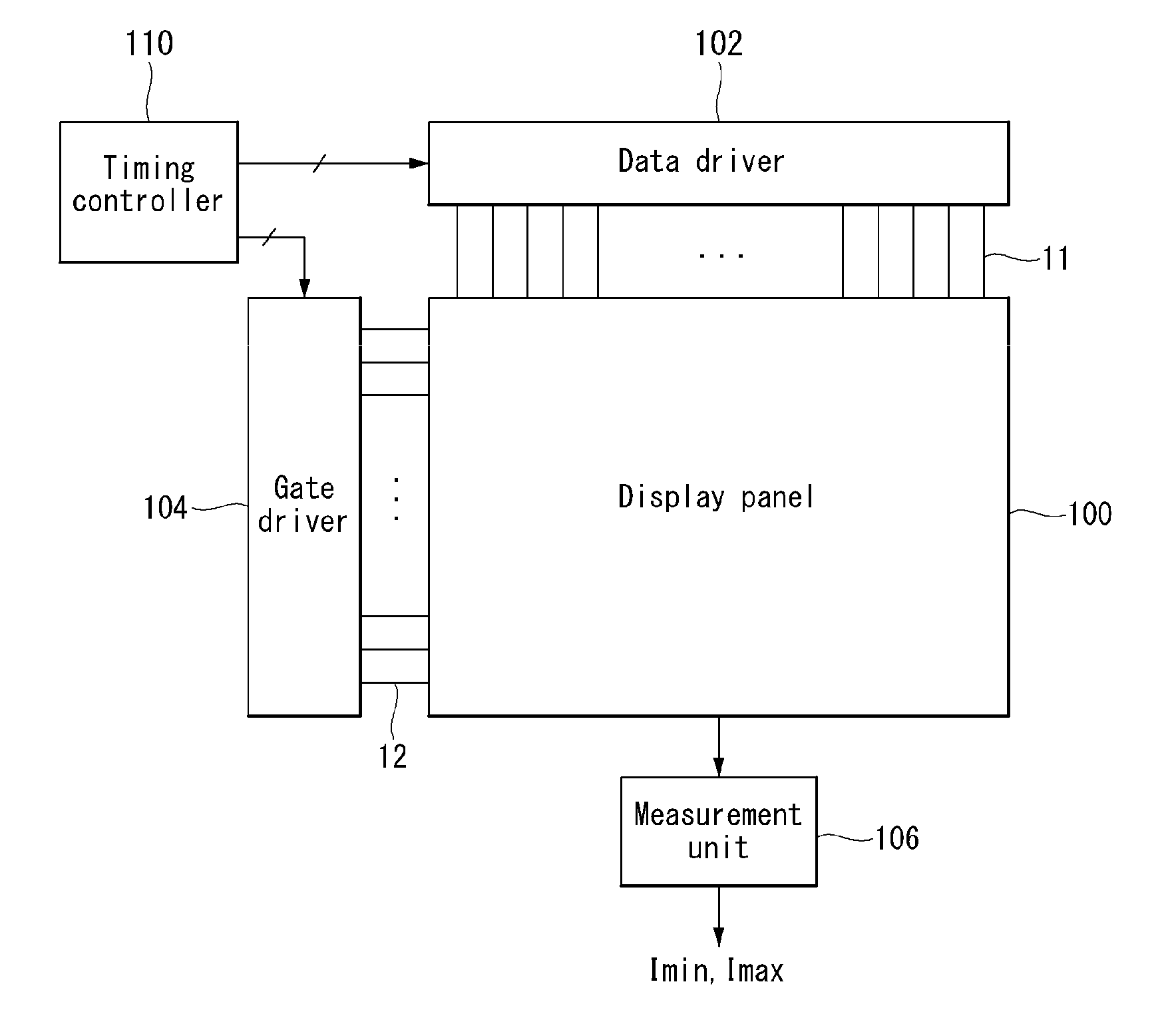
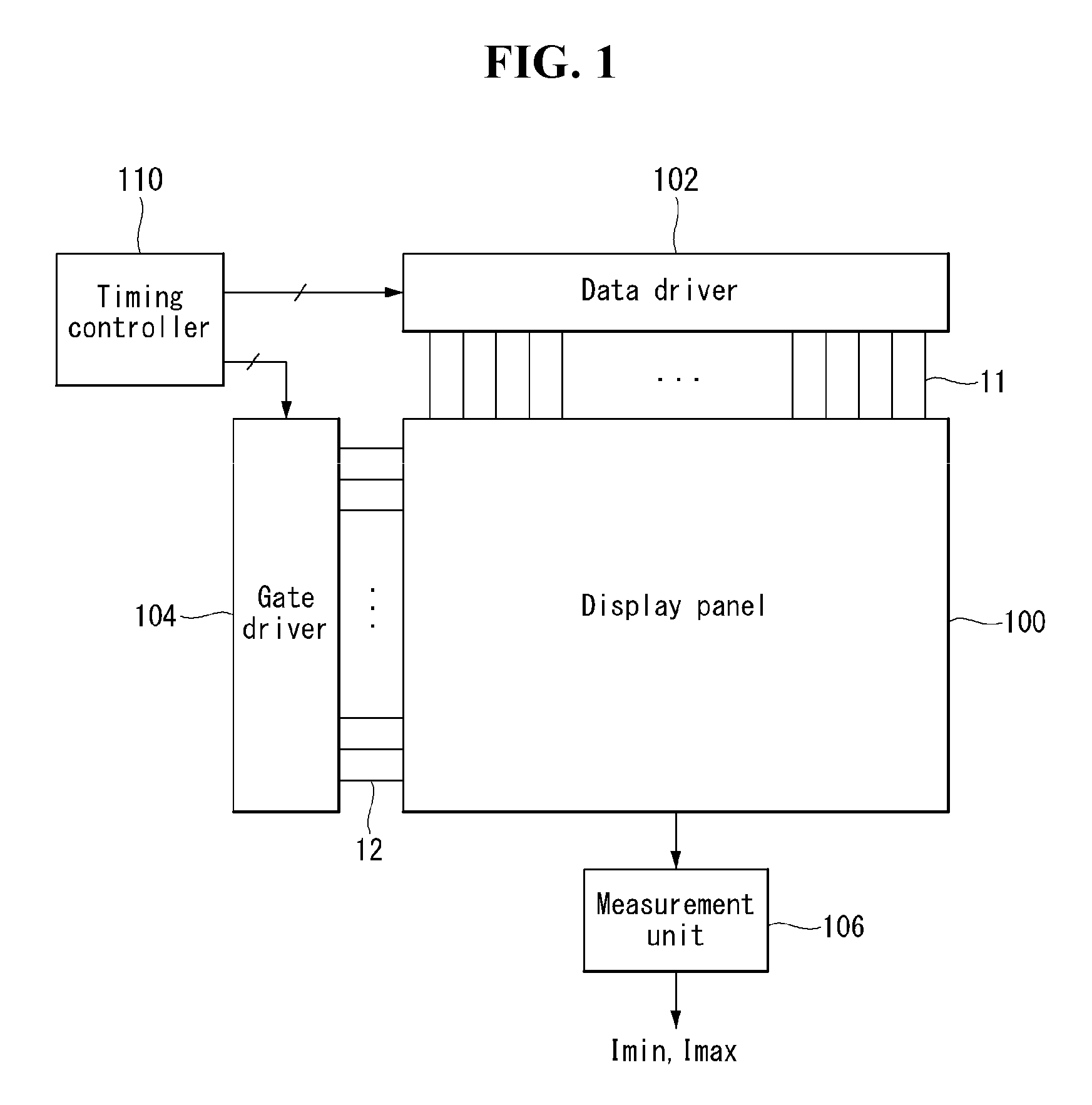
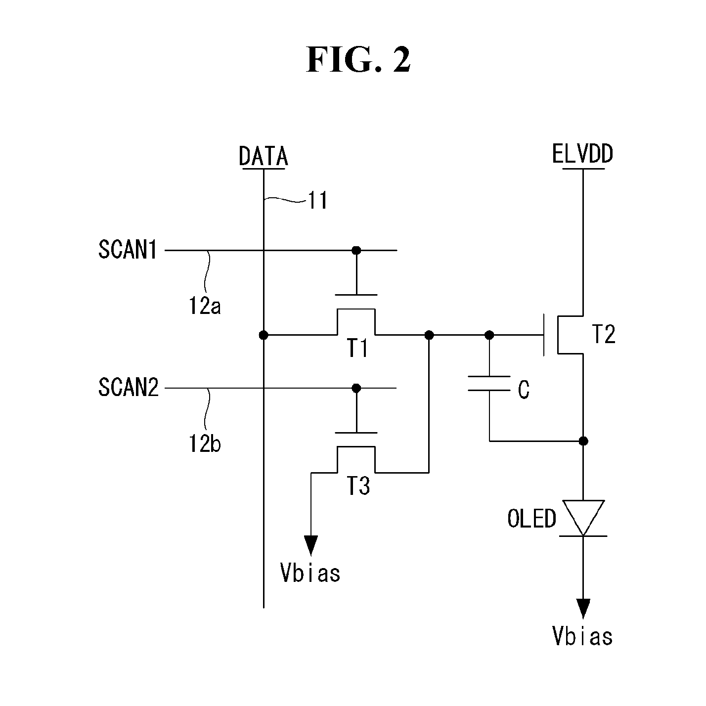
[0027]FIGS. 1 and 2 show a display device according to an example embodiment of the invention.

[0028]With reference to FIGS. 1 and 2, the display device according to an example embodiment of the invention includes a display panel 100, a display panel driver writing pixel data of an input image on a pixel array of the display panel 100 and including data driver 102 and gate driver 104, a measurement unit 106 measuring a current of a pixel, and a timing controller 110 controlling the display panel driver.

[0029]In the pixel array of the display panel 100, a plurality of data lines 11 and a plurality...


PUM


Abstract

A display device is provided for dividing one frame period into a plurality of subframe periods, separating data of an input image on a per bit basis, mapping the data of the input image to the subframe periods, and representing gray levels of the input image. The display device includes a measurement unit configured to measure a current of a pixel; a luminance error calculation unit configured to calculate a rush current of the pixel emitting light at the measured current value, and to calculate a luminance error of the pixel based on the rush current; and a luminance error compensation unit configured to reduce an emission time of one of the subframe periods or remap the subframe periods to compensate for the luminance error.

Description

[0001]This application claims the benefit of Korean Patent Application No. 10-2014-0190752, filed on Dec. 26, 2014, the entire contents of which are incorporated herein by reference for all purposes as if fully set forth herein.BACKGROUND OF THE INVENTION[0002]1. Field of the Invention[0003]Embodiments of the invention relate to a display device and, more particularly, to a display device having a self-calibration method thereof.[0004]2. Discussion of the Related Art[0005]Various flat panel displays, such as a liquid crystal display (LCD), an organic light emitting diode (OLED) display, a plasma display panel (PDP), and a field emission display (FED), have been used.[0006]The liquid crystal display typically displays an image by controlling an electric field applied to liquid crystal molecules based on a data voltage. Within the field of LCDs, an active matrix liquid crystal display reduces the manufacturing cost and improves performance due to the development of process technology ...

Claims


Application Information

Patent Timeline
Patent Type & Authority Applications(United States)
IPC IPC(8): G09G3/32G09G3/20
CPCG09G3/3258G09G3/2022G09G2320/0233G09G2330/021G09G2310/08G09G2360/16G09G3/3225G09G2300/0861G09G2320/0266G09G2320/029G09G2320/0693G09G2330/025H10K59/84H10K59/86H10K59/00G09G2320/045
Inventor PARK, DONGWONKWON, YONGCHUL
Owner LG DISPLAY CO LTD
Why Eureka
Try Eureka