Method and Assembly for Radio-Frequency (RF) Power Coupling

a radio frequency and power coupling technology, applied in the direction of coupling devices, basic electric elements, electrical equipment, etc., can solve the problems of high volume respectively size, lack of compactness, and inability to use high voltage, etc., to achieve low cost, high power, and easy assembly and manufacturing

Inactive Publication Date: 2016-06-30
OOO SIEMENS
View PDF2 Cites 1 Cited by
  • Summary
  • Abstract
  • Description
  • Claims
  • Application Information

AI Technical Summary

Benefits of technology

[0011]In view of the foregoing, it is an object of the present invention to provide a compact assembly for radio-frequency power coupling, which is easy to assemble and manufacture at low cost, and which can be used in high power applications. A further object of the present invention is to provide a method for using the assembly in a compact way.

Problems solved by technology

PCB based devices are quite compact but are not for use in high power applications.
A disadvantage of coaxial based combiners / dividers is the lack of compactness, i.e., high volume respectively size.
The device contains PCB, which does not enable high voltage use.
This conventional power combiner / divider is relatively large in size and is not compact, and due to its cylindrical shape it cannot be used in racks.
There is excessive empty space within the structure of the power combiner / divider.
Due to its PCB basing, this system can only be used in low power applications.
Further, the handling and manufacturing or the system is not easy.

Method used


Image

  • Method and Assembly for Radio-Frequency (RF) Power Coupling
  • Method and Assembly for Radio-Frequency (RF) Power Coupling
  • Method and Assembly for Radio-Frequency (RF) Power Coupling

Examples


Embodiment Construction

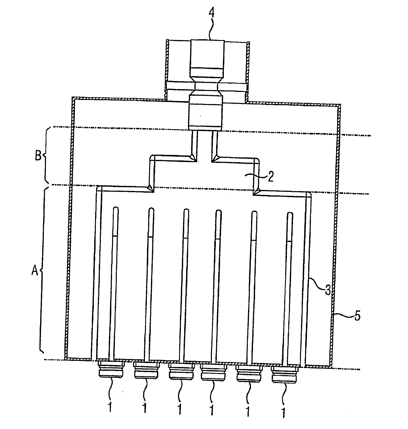
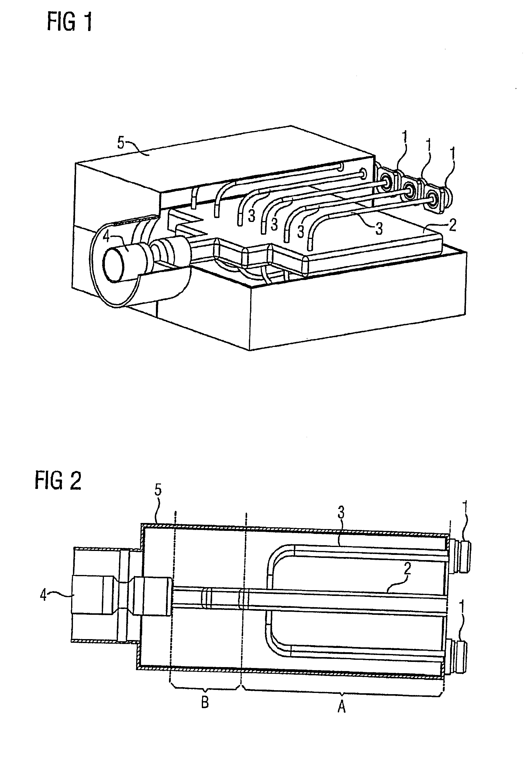
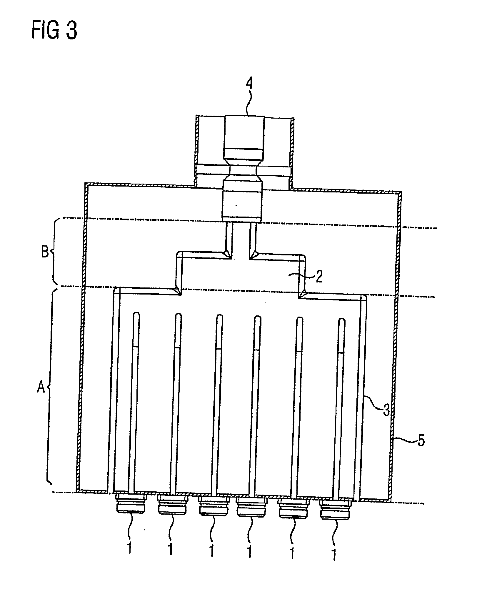
[0034]A power combiner / divider of an assembly in accordance with the present invention in a perspective view is shown in FIG. 1. The internal view to the inner parts of the power combiner / divider is enabled by leaving out a part of the outer casing 5. The power combiner / divider has the shape of a rectangular box, with multiple connectors for RF-power 1 on one side, and a connector for RF-power 4 on the opposite side of the box shaped casing 5. This arrangement is one possible embodiment, other arrangements are not shown in the FIG. 1 for purposes of simplicity.

[0035]Inside the casing 5, a flat center conductor 2 is arranged parallel to the ground plane of the box shaped casing 5. The center conductor 2 is directly connected in an electrically conductive manner to the connector for RF-power 4. The multiple connectors for RF-power 1 are each electrically conductively connected to the center conductor 2 via conductors 3 inside the box, which have the shape of bent rods with round cross...


PUM


Abstract

A method and an assembly for radio-frequency (RF) power coupling in a rack includes at least one box shaped power combiner and/or divider, connectors for inputting and outputting RF-power, conductors arranged inside the at least one box shaped power combiner and/or divider, electrically connecting the connectors with at least one center conductor, and at least one outside conductor formed as a box shaped casing.

Description

CROSS-REFERENCE TO RELATED APPLICATIONS[0001]This is a U.S. national stage of application No. PCT / RU2013 / 000708 filed 15 Aug. 2013.BACKGROUND OF THE INVENTION[0002]1. Field of the Invention[0003]The present invention relates to a method and assembly for radio-frequency power coupling, comprising at least one box shaped power combiner and / or divider, with connectors for input and output of RF-power, with conductors inside the box, electrically connecting the connectors with at least one center conductor, and with at least one outside conductor.[0004]2. Description of the Related Art[0005]Power dividers are used to divide RF power from single RF generators to multiple recipients. Power combiners are used to combine RF power from multiple sources to feed a single recipient with additional power. Recipients receiving RF power are, for example, loads or antennas. Most devices used as power divider or power combiner are also work reciprocally, i.e., they can be used both as a divider and ...

Claims


Application Information

Patent Timeline
Patent Type & Authority Applications(United States)
IPC IPC(8): H01P5/12H01P1/30
CPCH01P1/30H01P5/12
Inventor GUDOVICH, ALEXEYKRASNOV, ANDREYNIKOLSKIY, KONSTANTINSMIRNOV, ALEXANDER
Owner OOO SIEMENS
Why Eureka
Try Eureka