

Information processing apparatus, control method of the same, and video camera
a technology of information processing apparatus and control method, which is applied in the field of arithmetic technique of coordinate transformation matrix, can solve the problems of increasing operation error on numerical calculations and large operation amoun
- Summary
- Abstract
- Description
- Claims
- Application Information
AI Technical Summary
Benefits of technology
Problems solved by technology
Method used
Image

Examples
first embodiment
[0030]An example in which the present invention is applied to a video camera having a vibration-proofing function as an information processing apparatus for deducing a homography matrix will be explained below. FIG. 8 is a block diagram of main portions of the video camera according to the embodiment. The constituent elements and their functions will be explained below with reference to FIG. 8.
[0031]A controller 801 controls the whole apparatus, and includes a processor such as a CPU. The controller 801 also includes a memory 801a storing procedures (programs). An operation unit 802 for accepting instructions from an operator is connected to the controller 801. An imaging unit 803 includes an optical lens and imaging element, acquires, for example, image data of 30 frames per 1 sec, and alternately stores frame images one by one in frame memories 805 and 806 via a switch 804. As a consequence, the frame memories 805 and 806 hold two temporally consecutive frame images. A blurring de...
second embodiment
[0050]When three arbitrary feature points of four feature point coordinates are arranged on a straight line, a homography matrix cannot correctly be deduced any longer because of its properties. Therefore, the linearity of selected feature points is determined, and, if it is determined that the feature points have linearity, homography matrix deduction using the selected feature points is aborted. Consequently, a deducing process time after that can effectively be used in a homography matrix deducing process for other feature points. The second embodiment discloses a method of implementing this linearity determination with almost no additional processing.
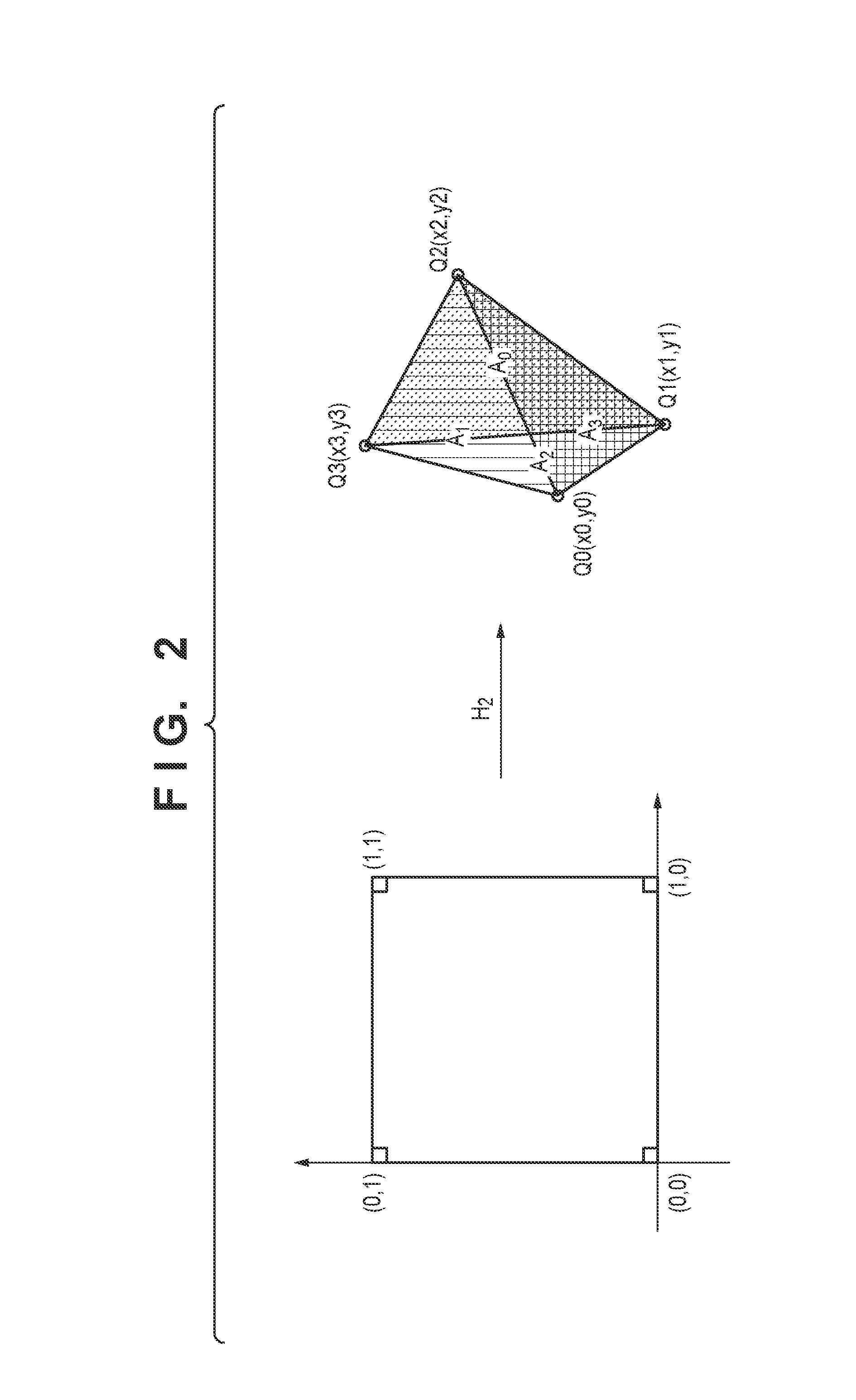
[0051]As disclosed in the first embodiment, equation (6) shows that g+1 and h+1 are respectively the area ratios ΔQ0Q2Q3 / ΔQ1Q2Q3 and ΔQ1Q2Q0 / ΔQ1Q2Q3 of triangles formed by the feature points. From this property, the linearity of feature points can easily be determined by using the area value of each triangle calculated during the pr...
third embodiment
[0057]The third embodiment shows an example in which the present invention is applied to a three-dimensional space, and a projective transformation matrix P from space 1 to space 2 is obtained.
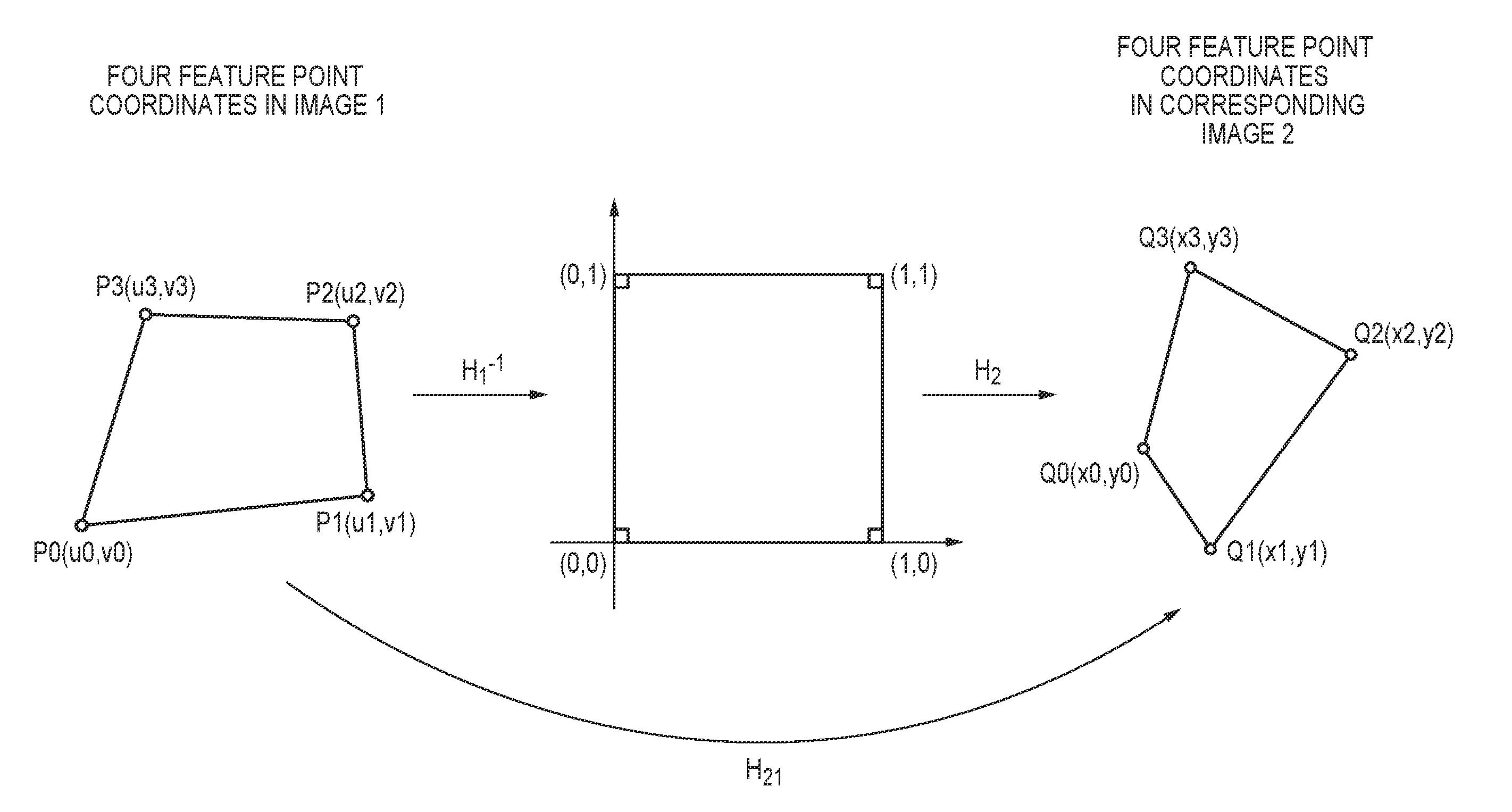
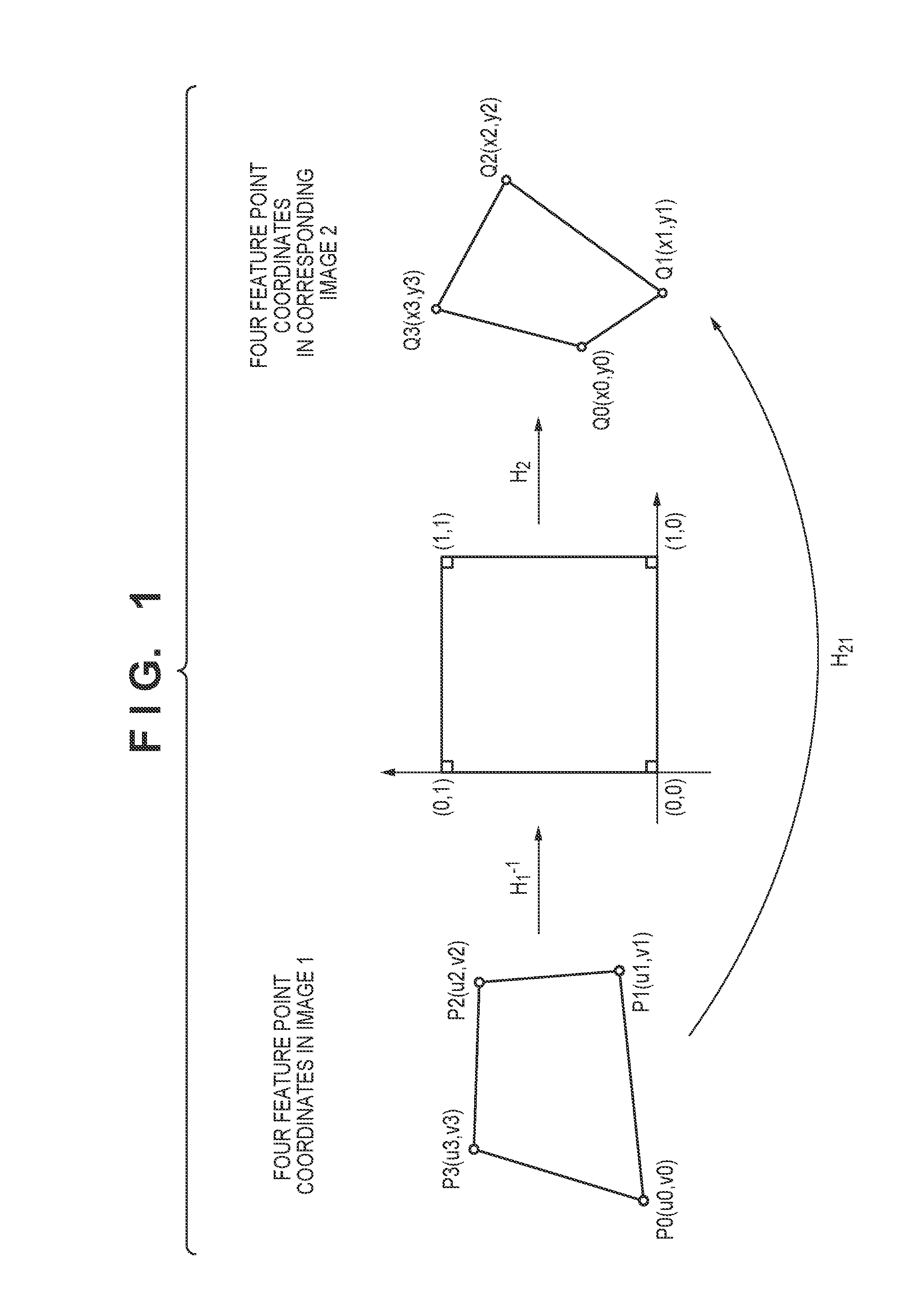
[0058]As in the first embodiment, a three-dimensional projective transformation matrix P can be decomposed into a projective transformation matrix P1−1 representing mapping from feature points in space 1 to reference coordinates, and a projective transformation matrix P2 representing mapping from the reference coordinates to feature points in space 2. The reference coordinates for obtaining the three-dimensional projective transformation matrix are five apexes of a unit cube in three-dimensional coordinates.
[0059]First, therefore, the calculation of the projective transformation matrix P2 representing mapping from the five apexes of the unit cube to the feature points in space 2 as shown in FIG. 5 will be explained.
[0060]An origin (0, 0, 0) and fourth unit coordinates (1, 0, 0), (0, 1, 0), (0,...
PUM
 Abstract
Description
Claims
Application Information