

Display panel
a display panel and panel technology, applied in the field of display panels, can solve the problems of difficult principle to completely eliminate the frame region, and achieve the effect of preventing the degradation of display quality
- Summary
- Abstract
- Description
- Claims
- Application Information
AI Technical Summary
Benefits of technology
Problems solved by technology
Method used
Image

Examples
embodiment 1
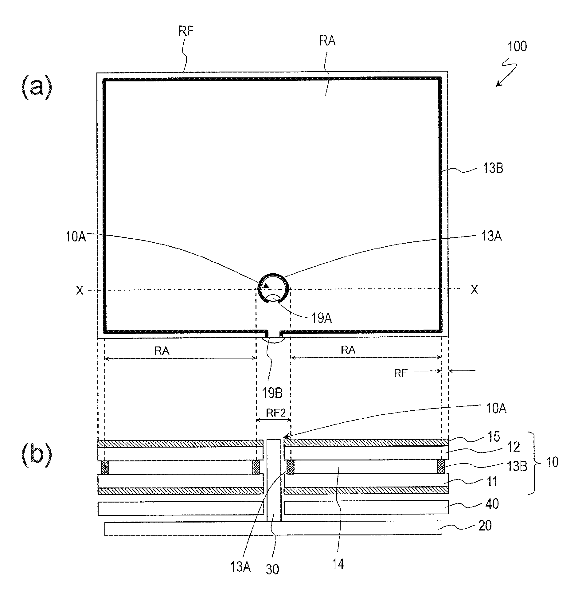
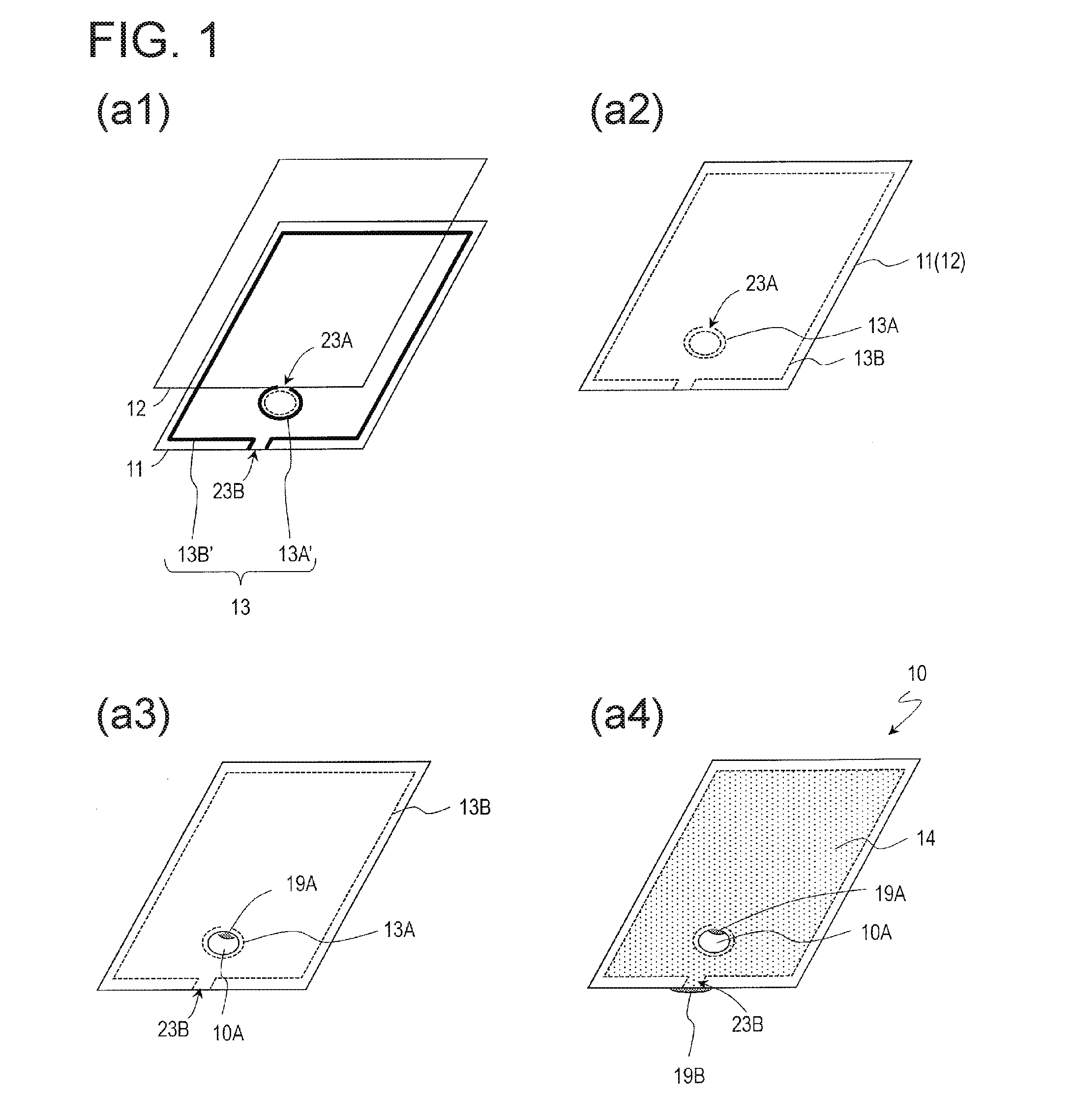
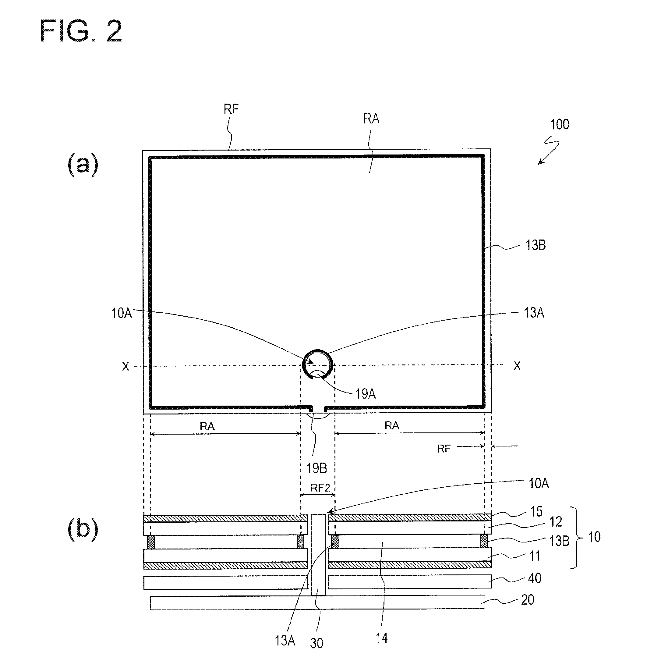
[0056]FIGS. 1(a1) to 1(a4) are perspective views showing part of a manufacturing process of a liquid crystal panel according to Embodiment 1.
[0057]After manufacturing the TFT substrate 11 and the opposite substrate 12 by a known method, as shown in FIG. 1(a1), the sealing member 13 is provided on one of the substrates (here, the TFT substrate 11).
[0058]The sealing member 13 is provided in a line-shape having a width of approximately 1 mm using a known dispenser device, for example. An ultraviolet curable or thermosetting resin material (acrylic resin or the like) can be used as a material for the sealing member 13, and “Photolec,” which is a UV curable sealing member made by Sekisui Chemical Co., Ltd., or the like can be used, for example.
[0059]In the process of providing the sealing member 13, an outer sealing member 13B′ having an outer frame-shape is provided on the periphery of the TFT substrate 11, and a hole-periphery sealing member 13A′ is provided around the area where the t...
embodiment 2
[0108]FIGS. 5(a1) and 5(a2) are perspective views showing part of a manufacturing process of a liquid crystal panel according to Embodiment 2, FIGS. 5(b1) and 5(c1) are cross-sectional views that correspond to the FIG. 5(a1), and FIGS. 5(b2) and 5(c2) are cross-sectional views that correspond to FIG. 5(a2). FIGS. 5(b1) and 5(b2) and FIGS. 5(c1) and 5(c2) show liquid crystal panels of a different configuration, respectively.
[0109]As shown in FIG. 5(a1), in the present embodiment, a structure 33 formed by a resin or the like is provided in the location that corresponds to an open section 23A of a hole-periphery sealing member 13A′ provided on a TFT substrate 11. As shown in FIG. 5(a2), in the substrate bonding process, the hole-periphery sealing member 13A′ is flattened so as to form a hole-periphery sealing part 13A in a closed-loop shape, which includes the structure 33.
[0110]Providing the structure 33 in advance on the TFT substrate 11 makes it no longer necessary, as it was in Emb...
embodiment 3
[0128]FIGS. 8(a1) to 8(a4) are perspective views showing part of a manufacturing process of a liquid crystal panel according to the present embodiment. FIGS. 8(b1) and 8(c1) are cross-sectional views that correspond to FIG. 8(a1), and FIGS. 8(b2) and 8(c2) are cross-sectional views that correspond to FIG. 8(a2). FIGS. 8(b1) and 8(b2) and FIGS. 8(c1) and 8(c2) show liquid crystal panels of a different configuration, respectively.
[0129]Unlike Embodiments 1 and 2, in which the sealing member 13A′ used to form the hole-periphery sealing part 13A on one of the substrates had a shape of a broken loop having an open section, a hole-periphery sealing part 13A in the present embodiment is formed by providing a sealing member in a dot shape or a planer shape and pushing and spreading the sealing member. A more specific description will be provided below.
[0130]First, a TFT substrate 11 and an opposite substrate 12 are prepared. However, in the present embodiment, a structure 33 is provided at ...
PUM
| Property | Measurement | Unit |
|---|---|---|
| diameter | aaaaa | aaaaa |
| width | aaaaa | aaaaa |
| diameter | aaaaa | aaaaa |
Abstract
Description
Claims
Application Information