Counter-Flow Heat Exchanger for Battery Thermal Management Applications

a heat exchanger and battery technology, applied in the field of counter-flow heat exchangers for battery thermal management applications, can solve the problems of large amount of heat that needs to be dissipated, and the potential temperature differential between the individual battery cells within the overall battery unit, which is generally considered undesirabl

Active Publication Date: 2016-07-14
DANA CANADA CORP
View PDF2 Cites 85 Cited by
  • Summary
  • Abstract
  • Description
  • Claims
  • Application Information

AI Technical Summary

Benefits of technology

[0008]In accordance with an example embodiment of the present disclosure there is provided a heat exchanger for thermal management of a battery unit having a plurality of battery cell containers each housing one or more battery cells, comprising a main body portion having opposed ends and defining at least one primary heat transfer surface for surface-to-surface contact with a corresponding surface of at least one of the battery cell containers; a plurality of first fluid flow passages formed within the main body portion, each of the first fluid flow passages having a first end for inletting a fluid into the first fluid flow passages and a second end for discharging the fluid from the first fluid flow passages, the first and second ends defining a flow direction through the first fluid flow passages; a plurality of second fluid flow passages formed within the main body portion, each of the second fluid flow passages having a first end for inletting the fluid into the second fluid flow passages and a second end for discharging the fluid from the second fluid flow passages, the first and second ends defining a flow direction through the second fluid flow passages; wherein the first and second fluid flow passages are arranged so as to alternate through the main body portion and wherein the flow direction of the first fluid flow passages is opposite to the flow direction of the second fluid flow passages.
[0009]In accordance with another example embodiment of the present disclosure there is provided a battery unit comprising a plurality of battery cell containers each housing one or more battery cells, said plurality of battery cell containers being arranged in a stack; and a heat exchanger comprising: a main body portion having opposed ends and defining at least one primary heat transfer surface for surface-to-surface contact with a corresponding surface of at least one of said battery cell containers; a plurality of first fluid flow passages formed within said main body portion, each of said first fluid flow passages having a first end for inletting a fluid into said first fluid flow passages and a second end for discharging said fluid from said first fluid flow passages, said first and second ends defining a flow direction through said first fluid flow passages; a plurality of second fluid flow passages formed within said main body portion, each of said second fluid flow passages having a first end for inletting said fluid into said second fluid flow passages and a second end for discharging said fluid from said second fluid flow passages, said first and second ends defining a flow direction through said second fluid flow passages; wherein said first and second fluid flow passages are arranged so as to alternate through said main body portion and wherein the flow direction of said first fluid flow passages is opposite to the flow direction of said second fluid flow passages; wherein said plurality of battery cell containers are arranged in a stack with each battery cell container being in surface-to-surface contact with the adjacent battery cell container, said stack of battery cell containers being arranged on top of and in thermal contact with said at least one primary heat transfer surface of said main body portion of said heat exchanger.
[0010]In accordance with a further example embodiment of the present disclosure there is provided a battery unit comprising a plurality of battery cell containers each housing one or more battery cells, said plurality of battery cell containers being arranged in a stack; and plurality of heat exchangers, wherein one heat exchanger is arranged in between adjacent battery cell containers, each heat exchanger comprising: a main body portion having opposed ends and defining at least one primary heat transfer surface for surface-to-surface contact with a corresponding surface of at least one of said battery cell containers; a plurality of first fluid flow passages formed within said main body portion, each of said first fluid flow passages having a first end for inletting a fluid into said first fluid flow passages and a second end for discharging said fluid from said first fluid flow passages, said first and second ends defining a flow direction through said first fluid flow passages; a plurality of second fluid flow passages formed within said main body portion, each of said second fluid flow passages having a first end for inletting said fluid into said second fluid flow passages and a second end for discharging said fluid from said second fluid flow passages, said first and second ends defining a flow direction through said second fluid flow passages; wherein said first and second fluid flow passages are arranged so as to alternate through said main body portion and wherein the flow direction of said first fluid flow passages is opposite to the flow direction of said second fluid flow passages; wherein said main body portion of said heat exchanger defines first and second primary heat transfer surfaces on opposed sides thereof; and wherein said plurality of heat exchangers are interconnected by a common inlet manifold and a common outlet manifold.
[0011]In accordance with yet another example embodiment of the present disclosure there is provided a method of making a heat exchanger for thermal management of battery units comprising the steps of providing a plurality of base plate portions, each base plate portion comprising a central, generally planar portion surrounded by a peripheral flange, a portion of said plurality of alternating first and second fluid flow passages being formed within the central generally planar portion of each of said base plate portions, said base plate portions being arranged adjacent to each other and fixed together to form said base plate; wherein said first and second fluid flow passages are formed by a plurality of U-shaped embossments formed in said central, generally planar portion of each of said base plate portions, said U-shaped embossments having two elongate branches that terminate at discrete ends wherein said first fluid flow passages are formed between adjacent U-shaped embossments and said second fluid flow passages being formed between the two elongate branches of each of said U-shaped embossments, the second ends of said first fluid flow passages and said first ends of said second fluid flow passages being interconnected by a common fluid collector channel that extends along the width of each of said base plate portions, the first ends of said first fluid flow passages being interconnected by a common inlet header region that extends along the width of each of said base plate portions; having the same structure; selecting a predetermined number of base plate portions for forming a heat exchanger having predetermined dimensions; arranging said predetermined number of base plate portions in side-by-side arrangement and joining said base plate portions together for forming a base plate; sealingly arranging a cover plate on top of said base plate for enclosing said first and second fluid flow passages, said cover plate comprising: a central, generally planar portion that defines a primary heat transfer surface for contacting at least one battery cell or battery cell container; one or more fluid routing slots formed in said cover plate, each fluid routing slot being in communication with said inlet header region formed in each of said base plate portions; a series of fluid openings formed in said cover plate inset from said fluid routing slots and extending along the width of the cover plate, each fluid opening being in communication with a corresponding second end of said second fluid flow passages formed in said base plate portions; and sealingly arranging a manifold cover on said cover plate enclosing said fluid routing slots and said series of fluid openings for forming respective inlet and outlet manifolds for inletting and discharging a heat exchange fluid into said heat exchanger.

Problems solved by technology

These applications often require advanced battery systems that have high energy storage capacity and can generate large amounts of heat that needs to be dissipated.
As a result of the inherent temperature differential across the surface of the heat exchanger, battery cells arranged proximal to the inlet end of the heat exchanger will be subject to a lower coolant temperature than battery cells arranged proximal to the outlet end of the heat exchanger resulting in a potential temperature differential between the individual battery cells within the overall battery unit which, generally, is considered undesirable.

Method used


Image

  • Counter-Flow Heat Exchanger for Battery Thermal Management Applications
  • Counter-Flow Heat Exchanger for Battery Thermal Management Applications
  • Counter-Flow Heat Exchanger for Battery Thermal Management Applications

Examples


Embodiment Construction

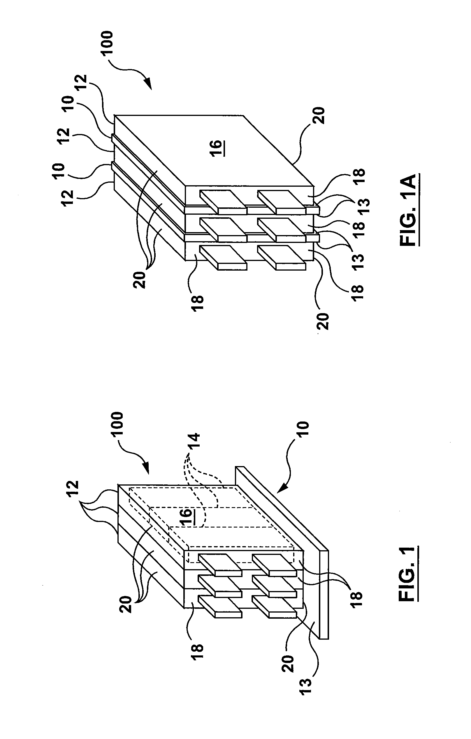
[0053]Referring now to FIG. 1, there is shown a schematic, illustrative example of a rechargeable battery unit 100 employing a battery cooling heat exchanger 10. The battery unit 100 is made up of a series of individual battery cell containers 12 that may each house one or more battery cells 14. While three individual battery cells 14 are schematically illustrated in FIG. 1, it will be understood that the number of battery cells 14 housed within the battery cell container 12 may vary depending upon the particular design and / or application of the battery unit 100 and that the present disclosure is not intended to be limited to battery units having three battery cell containers 12 with three battery cells 14 arranged therein.

[0054]The individual battery cell containers 12 that house the one or more battery cells 14 each define a pair of opposed long, side faces 16, a pair of opposed, short side faces 18 and a pair of end faces 20 arranged generally perpendicular to the side faces 16, ...


PUM

PropertyMeasurementUnit
heat transferaaaaaaaaaa
lengthaaaaaaaaaa
distanceaaaaaaaaaa

Abstract

A heat exchanger for thermal management of battery units made-up of plurality of battery cells or battery cell containers housing one or more battery cells is disclosed. The heat exchanger has a main body portion defining at least one primary heat transfer surface for surface-to-surface contact with a corresponding surface of at least one of the battery cells or containers. A plurality of alternating first and second fluid flow passages are formed within the main body portion each defining a flow direction, the flow direction through the first fluid flow passages being generally opposite to the flow direction through the second fluid flow passages providing a counter-flow heat exchanger. In some embodiments the heat exchanger has a two pairs of inlet and outlet manifolds, the heat exchanger providing a single-pass, counter-flow arrangement. In other embodiments the first and second fluid flow passages are interconnected by turn portions forming a U-flow, counter-flow heat exchanger.

Description

CROSS-REFERENCE TO RELATED APPLICATION[0001]This application claims priority to and the benefit of U.S. Provisional Patent Application No. 62 / 101,527, filed Jan. 9, 2015 under the title COUNTER-FLOW HEAT EXCHANGER FOR BATTERY THERMAL MANAGEMENT APPLICATIONS. The content of the above patent application is hereby expressly incorporated by reference into the detailed description of the present application.TECHNICAL FIELD[0002]This disclosure relates to heat exchangers for battery thermal management applications. More specifically, the disclosure relates to a battery cell heat exchanger that can be arranged underneath a stack of a plurality of adjacent battery cells or battery cell containers or that can be arranged in between the adjacent battery cells or battery cell containers within a stack, the battery cell heat exchanger dissipating heat in rechargeable battery units.BACKGROUND[0003]Rechargeable batteries such as batteries made up of many lithium-ion cells can be used in many appl...

Claims


Application Information

Patent Timeline
Patent Type & Authority Applications(United States)
IPC IPC(8): H01M10/6556B23P15/26
CPCB23P15/26H01M10/6556H01M10/6568H01M10/617H01M10/613F28F3/12F28F1/022F28F1/045F28F2009/0297Y02P70/50Y02E60/10F28D2021/0043
Inventor KENNEY, BENJAMIN A.BUCKRELL, ANDREW J.M.SHORE, COLIN A.VANDERWEES, DOUGABELS, KENNETH M.A.
Owner DANA CANADA CORP
Why Eureka
Try Eureka