
System and Method for Synchronizing Multiple Oscillators Using Reduced Frequency Signaling

a signaling system and signaling technology, applied in the field of system and method of synchronizing multiple oscillators using reduced frequency signaling, can solve the problems of limiting scalability and flexibility, increasing or decreasing the number of channels, and designing such multiple interlocked rfs

Active Publication Date: 2016-07-14
INFINEON TECH AG
View PDF1 Cites 9 Cited by
  • Summary
  • Abstract
  • Description
  • Claims
  • Application Information

AI Technical Summary

Benefits of technology

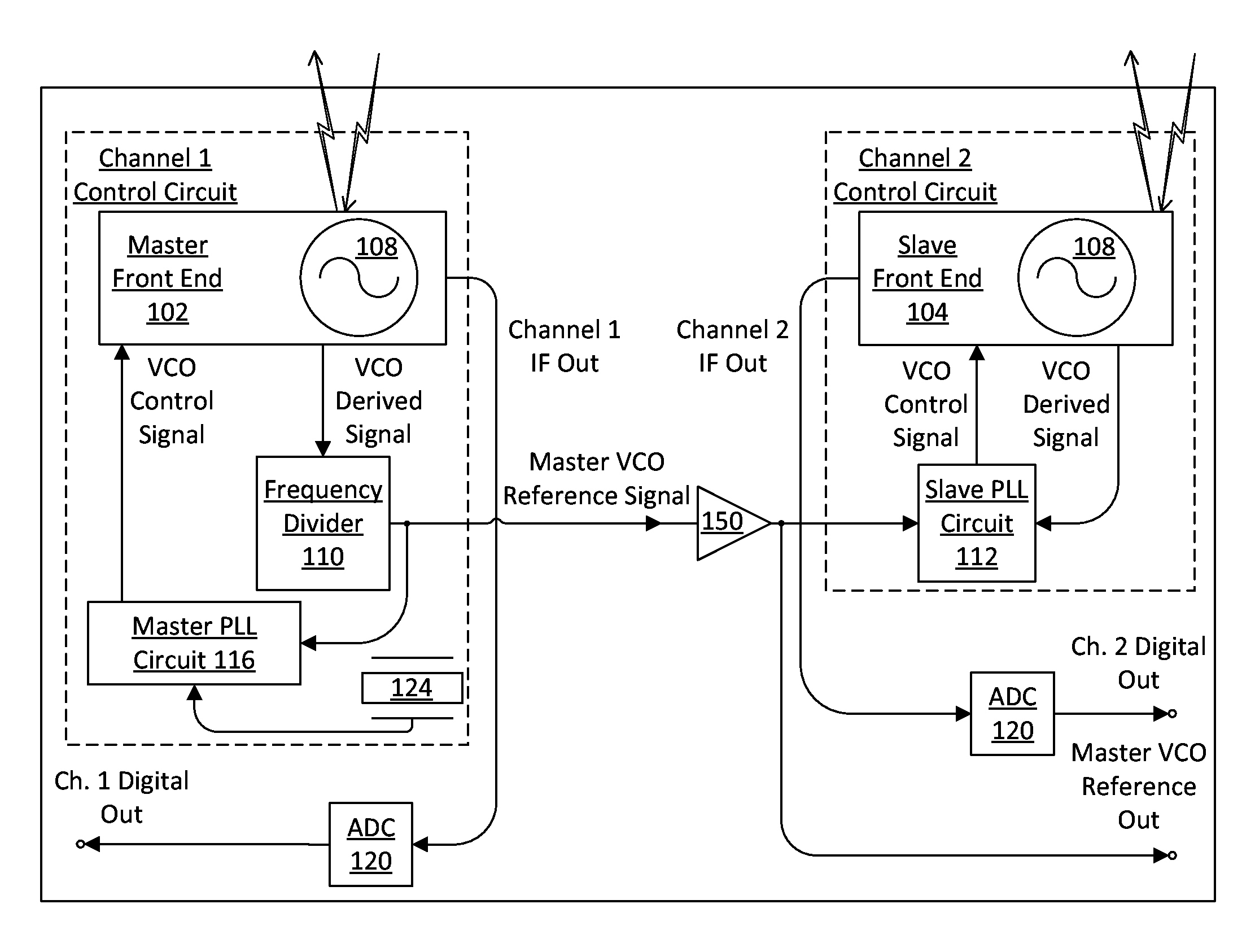
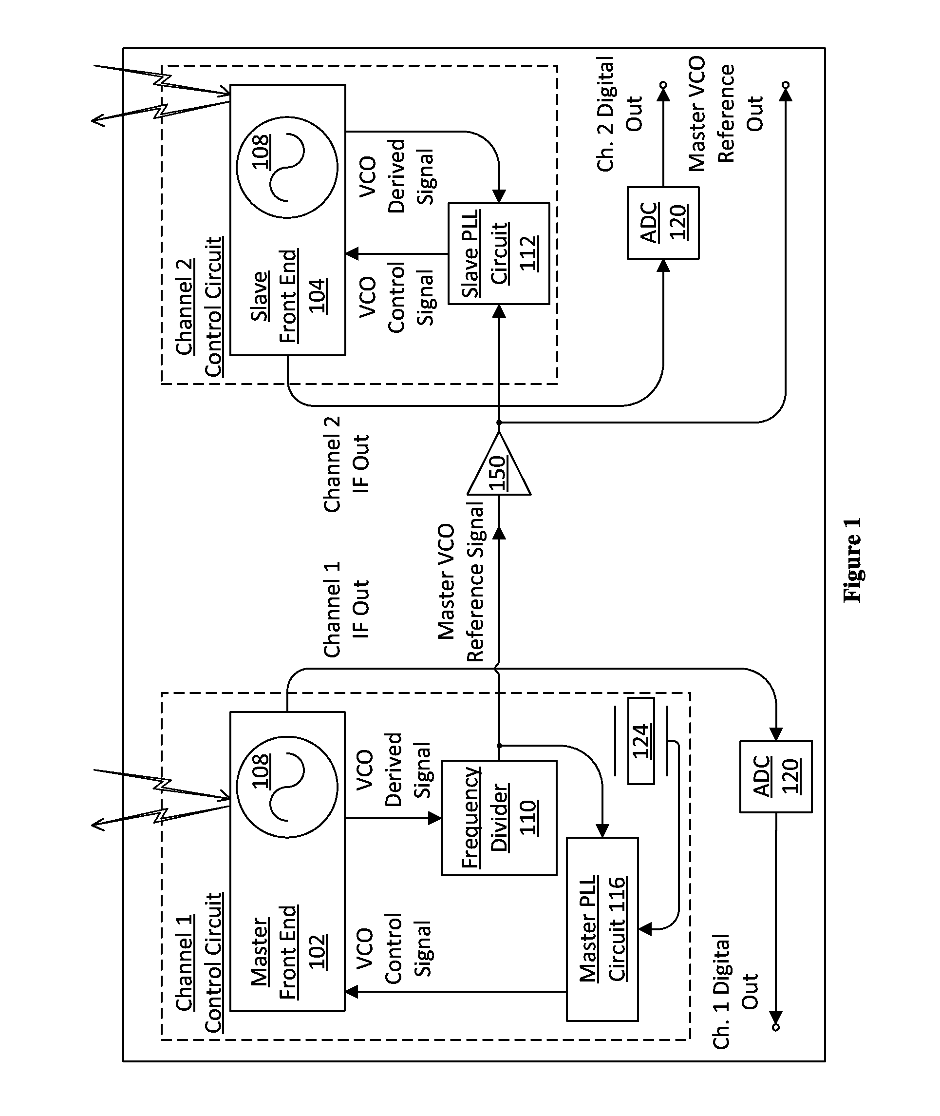
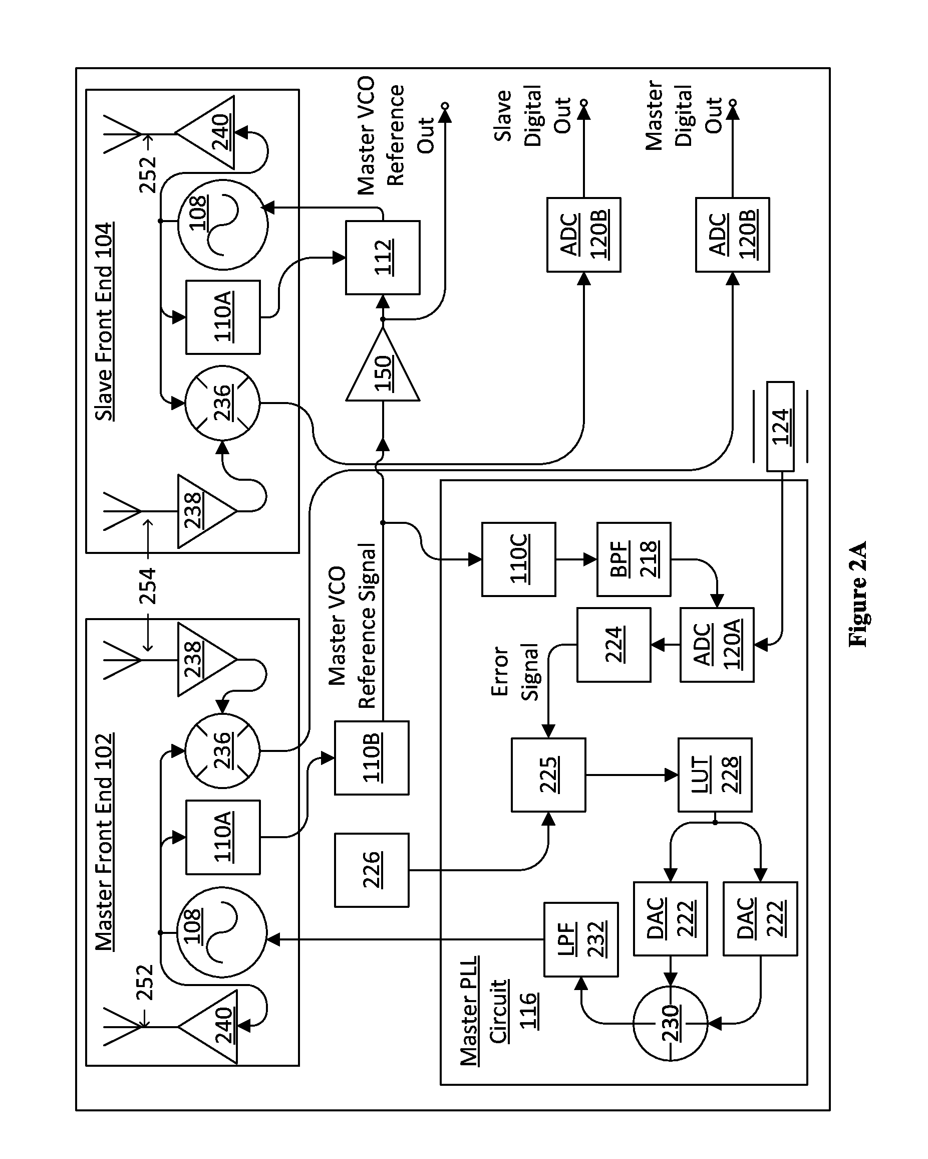
The present invention provides a method for controlling the output frequency of a voltage-controlled oscillator (VCO) in a system by detecting the first VCO output signal and using a first interpolation circuit to determine a first down-scaled signal. This down-scaled signal is then used to modify the first VCO output frequency using a first phase lock loop (PLL) and detect the second VCO output signal. This process is repeated for the second VCO to modify its output frequency. The method results in improved phase lock and reduced bandwidth limitations. The system also includes a phased array beamforming system that utilizes master and slave satellites with VCOs and PLL circuits to control the output frequencies of the VCOs in a more efficient and accurate manner.

Problems solved by technology

Nevertheless, designing such multiple interlocked RF channels presents a number of challenges.
Yet in some applications these PCB antenna designs limit scalability and flexibility and make increasing or decreasing the number of channels more difficult.
Furthermore, for a given PCB material, energy losses increase with increasing channel frequency and trace length.
Regardless of antenna design, such increasing energy losses would be experienced if a single Local Oscillator (LO) operating at high radio frequencies were to be shared between separate channels to provide the mechanism of frequency-locking or jointly modulating the channels.

Method used


Image

  • System and Method for Synchronizing Multiple Oscillators Using Reduced Frequency Signaling
  • System and Method for Synchronizing Multiple Oscillators Using Reduced Frequency Signaling
  • System and Method for Synchronizing Multiple Oscillators Using Reduced Frequency Signaling

Examples


Embodiment Construction

[0014]The making and using of the presently preferred embodiments are discussed in detail below. It should be appreciated, however, that the present invention provides many applicable inventive concepts that can be embodied in a wide variety of specific contexts. The specific embodiments discussed are merely illustrative of specific ways to make and use the invention, and do not limit the scope of the invention.

[0015]The present invention will be described with respect to preferred embodiments in a specific context, a system and method for synchronizing multiple oscillators for use in an RF transceiver system such as an FMCW radar system or a phased array beamforming system. Further embodiments may be applied to other RF transmitter / receiver systems that require reduced frequency signaling to synchronize multiple oscillators for use in, for example, remote sensing, airport security screening, high-speed data links, high-speed wireless local area networks, and broadband Internet acce...


PUM


Abstract

An embodiment method for voltage-controlled oscillator (VCO) control includes detecting a first VCO output signal of a first VCO. The first VCO output signal has a first VCO output frequency. The method also includes determining a first down-scaled signal in accordance with the first VCO output signal. The first down-scaled signal has a first down-scaled frequency that is reduced by a fixed ratio relative to a current value of the first VCO output frequency. The method also includes modifying the first VCO output frequency using a first phase lock loop (PLL) in accordance with the first down-scaled signal and an oscillating reference signal, and detecting a second VCO output signal of a second VCO. The second VCO output signal has a second VCO output frequency. The method also includes modifying the second VCO output frequency in accordance with the second VCO output signal and the first down-scaled signal.

Description

TECHNICAL FIELD[0001]The present invention relates generally to a system and method for oscillator control, and, in particular embodiments, to a system and method for synchronizing multiple oscillators using reduced frequency signaling.BACKGROUND[0002]Radio-frequency (RF) transmitters and receivers having multiple high frequency channels that are frequency-locked or jointly modulated are useful for a variety of applications. These applications include remote sensing, radar, and airport security screening systems. High-speed data links, high-speed wireless local area networks, and broadband Internet access systems also can benefit from high frequency multi-channel RF implementations.[0003]Nevertheless, designing such multiple interlocked RF channels presents a number of challenges. RF transmitter and receiver systems are typically implemented on Printed Circuit Board (PCB), and the antennas of many systems are implemented using traces directly on the underlying PCB. Yet in some appli...

Claims


Application Information

Patent Timeline
Patent Type & Authority Applications(United States)
IPC IPC(8): H03L7/07H03L7/099H01Q3/30H03L7/093
CPCH03L7/07H01Q3/30H03L7/099H03L7/093
Inventor TROTTA, SAVERIOJUNGMAIER, REINHARD-WOLFGANG
Owner INFINEON TECH AG
Learn More