
Breast thickness measurement device and breast thickness measurement method

Active Publication Date: 2016-07-21
FUJIFILM CORP
View PDF13 Cites 10 Cited by
  • Summary
  • Abstract
  • Description
  • Claims
  • Application Information

AI Technical Summary

Benefits of technology

The present invention provides a device and method for measuring the thickness and radiation dose of a compressed breast. It accurately calculates the thickness of the breast from tomotic images and calculates the average glandular dose based on this thickness. This ensures accurate measurement of the dose of radiation required for normal image capturing after tomosynthesis image capturing. The device is designed to provide accurate results in breast cancer detection and treatment.

Problems solved by technology

In the event that the compressed breast is of a distorted shape, the thickness of the breast undergoes local variations, which tend to increase measurement errors of the position detecting sensor, and hence it becomes difficult to suitably measure the thickness of the breast.
Furthermore, since the thickness of the breast is measured at the proximal end portion of the compression plate, which is spaced from the compressed breast, measurement errors are likely to increase further.

Method used


Image

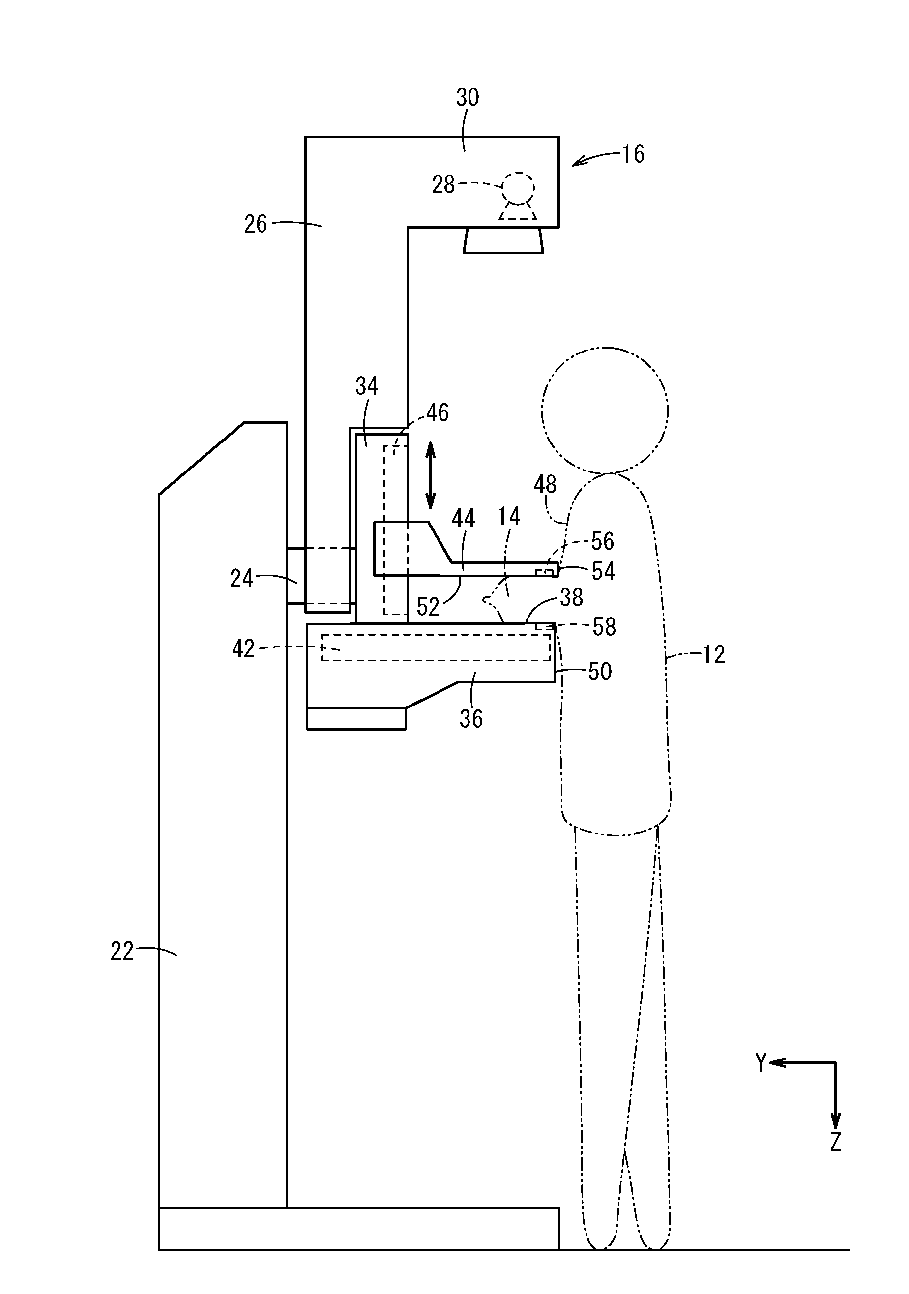
  • Breast thickness measurement device and breast thickness measurement method
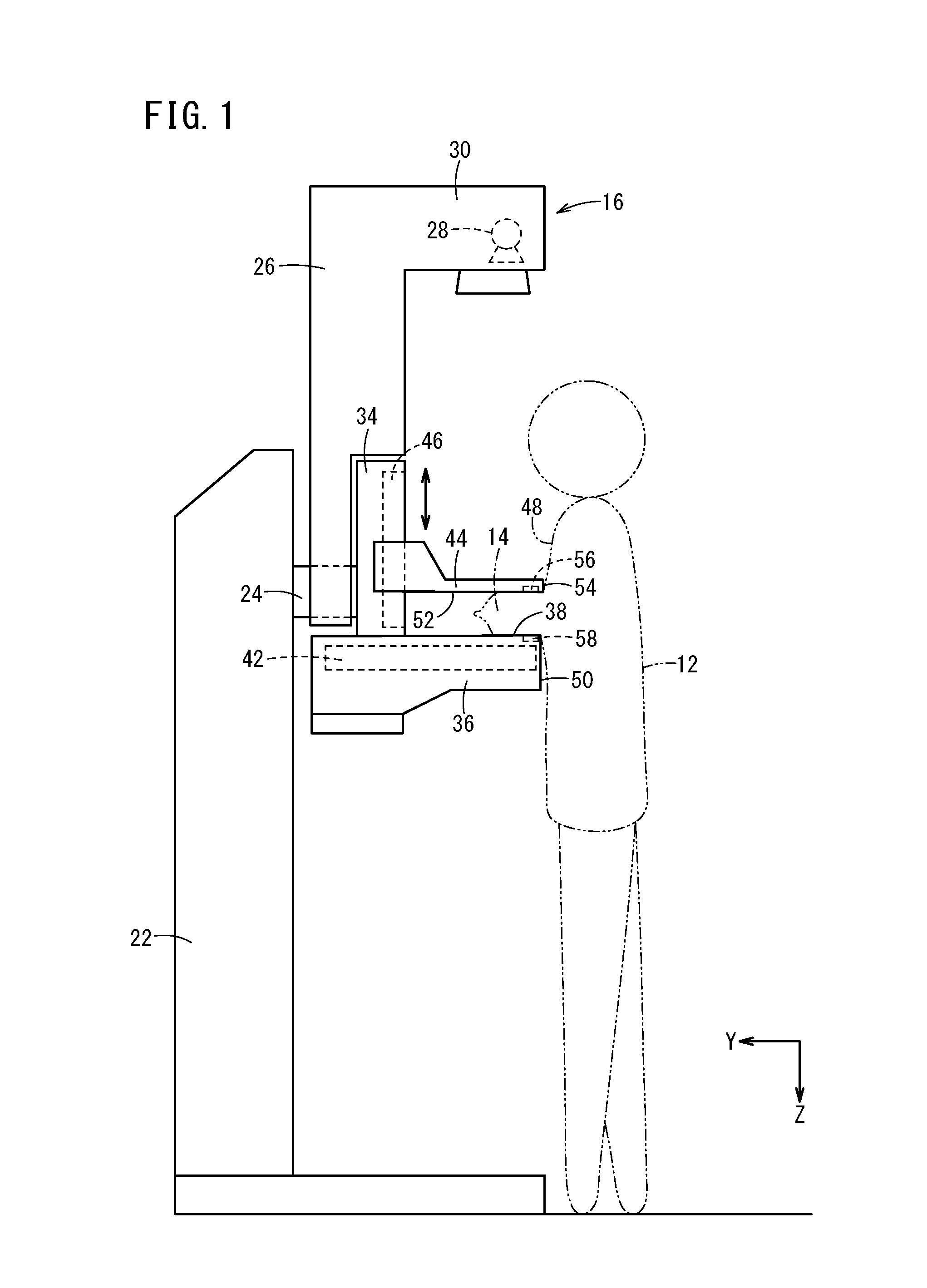
  • Breast thickness measurement device and breast thickness measurement method
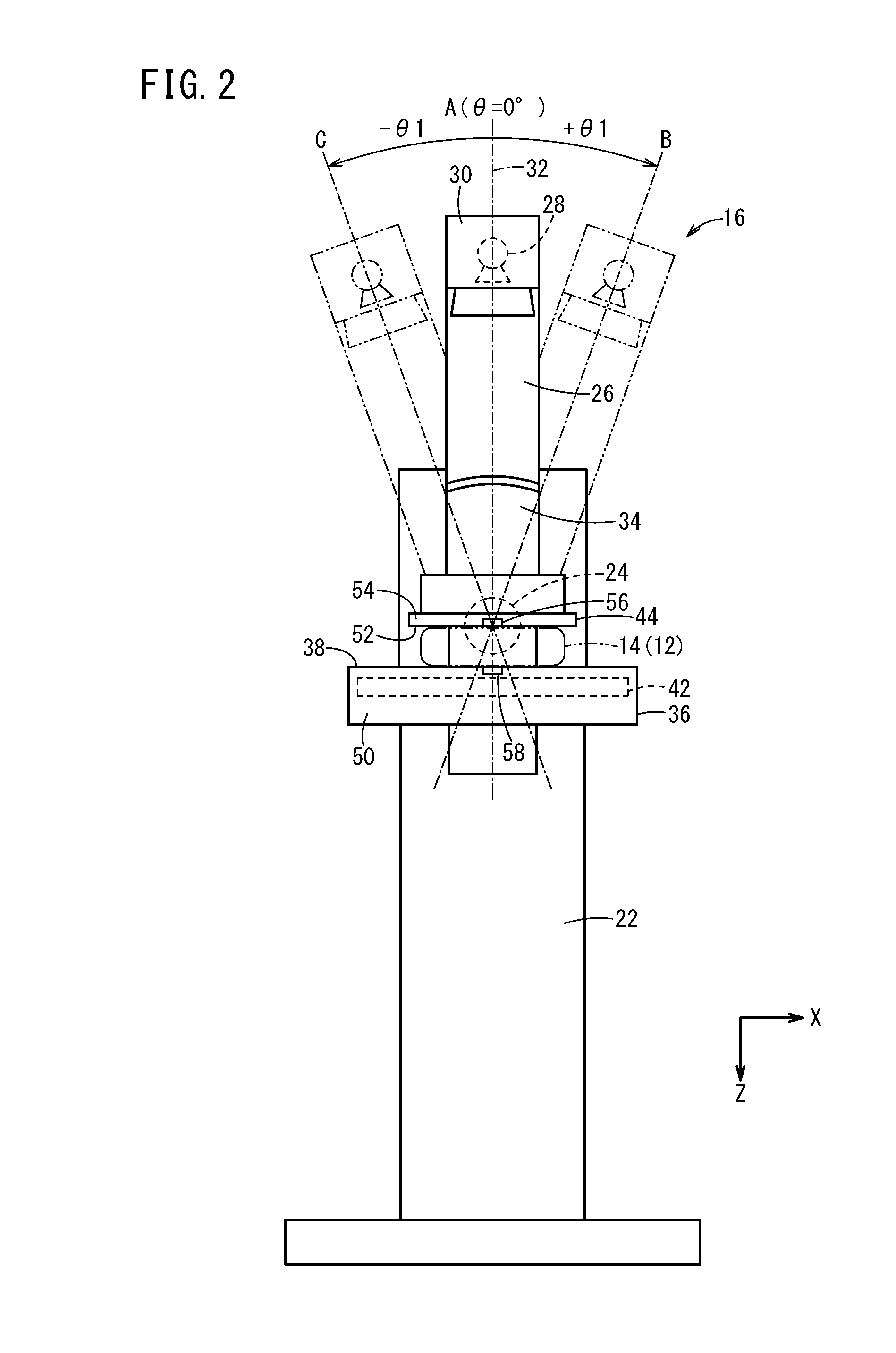
  • Breast thickness measurement device and breast thickness measurement method

Examples


first modification

[0147]According to the first modification, as shown in FIGS. 8 and 9, a shaft 114 is provided on a proximal end portion of the compression plate 44, and the compression plate 44 is arranged so as to be capable of moving angularly about the shaft 114. Therefore, in a case where the compression plate 44 is lowered toward the image capturing table 36 by the compression plate moving mechanism 46, and is brought into contact with the breast 14, the side of the compression plate 44 proximate the side surface 54 turns counterclockwise as shown in FIGS. 8 and 9 (toward the radiation source 28) about the shaft 114. Thus, the compression plate 44 compresses the breast 14 while being tilted along the breast 14. The angle sensor 98 is mounted on the shaft 114 for detecting the angle of tilt of the compression plate 44 with respect to the horizontal plane (i.e., the angle of the compression plate 44 before the compression plate 44 contacts the breast 14).

[0148]According to the first modification...

second modification

[0151]According to the second modification, as shown in FIGS. 10 through 13, the compression plate 44 is mounted on the holder 34 by a rotational shaft 116, and the compression plate 44 is arranged so as to be angularly movable about the rotational shaft 116. The angle α of tilt of the compression plate 44 with respect to the horizontal direction (the direction of the arrow X and the direction of the arrow Y) is detected by the angle sensor 99.

[0152]According to the second modification, first markers 56 are disposed on respective left and right corners (angular portions) along the direction of the arrow X proximate the side surface 54 of the compression plate 44. More specifically, according to the second modification, as shown in FIG. 12, the two first markers 56 are embedded in the compression plate 44 so as to lie substantially flush with the compression surface 52 at positions spaced Xm to the left and right from the central line 60, and also spaced Ym back from the side surface...

third modification

[0162]As shown in FIGS. 14 and 15, the third modification differs from the second modification (see FIGS. 10 through 13), in that a further first marker 56 is disposed at a central position (a position on the vertical axis 32) of the compression plate 44 proximate the side surface 54 thereof. Accordingly, the third modification is a combination of the arrangement of the embodiment shown in FIGS. 1 through 3 and the arrangement of the second modification shown in FIGS. 10 through 13.

[0163]According to the third modification, as shown in FIG. 15, in the case that the compression plate 44 is curved (curved in an upwardly convex manner as shown in FIG. 15), it is possible to grasp the degree to which the compression plate 44 is distorted.

[0164]More specifically, as shown in FIG. 15, assuming that the distance between the central first marker 56 and the placement surface 38 is represented by Zc, the central first marker 56 is captured in the first tomographic image 100, and the left and ...


PUM


Abstract

In this breast thickness measurement device and breast thickness measurement method, radiation is radiated from a plurality of different angles to a breast that is in a compressed state, a plurality of image data are generated by means of a radiation detector, and a plurality of tomographic images are generated by reconfiguring on the basis of each image datum after same has been generated. In each tomographic image, the thickness of the compressed breast is calculated on the basis of a tomographic image in which the focal point matches a first marker and a tomographic image in which the focal point matches a second marker.

Description

CROSS-REFERENCE TO RELATED APPLICATIONS[0001]This application is a Continuation of International Application No. PCT / JP2014 / 064610 filed on Jun. 2, 2014, which is based upon and claims the benefit of priority from Japanese Patent Application No. 2013-203536 filed on Sep. 30, 2013, the contents all of which are incorporated herein by reference.TECHNICAL FIELD[0002]The present invention relates to a breast thickness measuring device and a breast thickness measuring method for measuring the thickness of a breast of a subject that has been compressed by a support table and a compression plate.BACKGROUND ART[0003]Heretofore, for capturing a radiographic image of a breast of a subject using a radiographic image capturing apparatus, it has been customary to place the breast on a support table, displace a compression plate toward the support table to compress the breast, and thereafter, irradiate the breast with radiation emitted from a radiation source. Then, the radiation that has passed ...

Claims


Application Information

Patent Timeline
IPC IPC(8): A61B5/107A61B90/00A61B6/00A61B6/02A61B6/04
CPCA61B5/1075A61B6/025A61B2090/3966A61B6/502A61B90/39A61B6/0414
Inventor ARAI, TAKAHISAINOUE, TOMOKI
Owner FUJIFILM CORP
Learn More