High frequency Anti-scatter grid movement profile for line cancellation

a technology of anti-scatter grid and movement profile, which is applied in the field of medical imaging, can solve the problems of reducing the quality and legibility of the image obtained, affecting the accuracy of the image, so as to reduce the acceleration stress on the grid

Active Publication Date: 2016-07-21
GENERAL ELECTRIC CO
View PDF0 Cites 11 Cited by
  • Summary
  • Abstract
  • Description
  • Claims
  • Application Information

AI Technical Summary

Benefits of technology

[0019]As outlined above, none of these solutions gives a completely satisfactory result. In particular, even if the grid is no longer visible on the frame, a moire effect remains, linked to interference between the strips of the grid and the network of sensors of the detector.
[0020]What is needed, therefore, is an apparatus and process for making an image with a grid having strips parallel to the chest wall of the patient P, while at the same time avoiding any residual image of the grid strips or resulting moire patterns in the image.
[0021]Embodiments of the present invention provide a process and device for deploying an anti-scattering grid, applicable to mammography and to breast tomosynthesis, which eliminates both the image of the grid on the detector, residual shadows from return points, and the residual moire effects. The invention further decreases the acceleration stress on the grid, allowing for a wider range of materials to be chosen.

Problems solved by technology

One drawback of using such grids is that an image of the radio-adsorbing strips of the grid appears on the detector.
Also, alternating strips can cause interference figures, or moire effect, on the detector and deteriorate the quality and legibility of the image obtained.
A further problem with this displacement, if periodic in nature, is the creation of shadowing and decreased contrast caused by the return points of the radio-adsorbing grid strips.
Current patterns of grid movement which use a fixed frequency or amplitude for grid movement increase the risk of making shadows from the grid strip at the return points visible in the images.
However, by way of an illustrative example, for a 2 mm amplitude periodic movement and 50 ms exposure time this would require accelerations as high as 30 g, which cannot be achieved at acceptable bulk and cost with currently available technologies.
As outlined above, none of these solutions gives a completely satisfactory result.
In particular, even if the grid is no longer visible on the frame, a moire effect remains, linked to interference between the strips of the grid and the network of sensors of the detector.

Method used


Image

  • High frequency Anti-scatter grid movement profile for line cancellation
  • High frequency Anti-scatter grid movement profile for line cancellation
  • High frequency Anti-scatter grid movement profile for line cancellation

Examples


Embodiment Construction

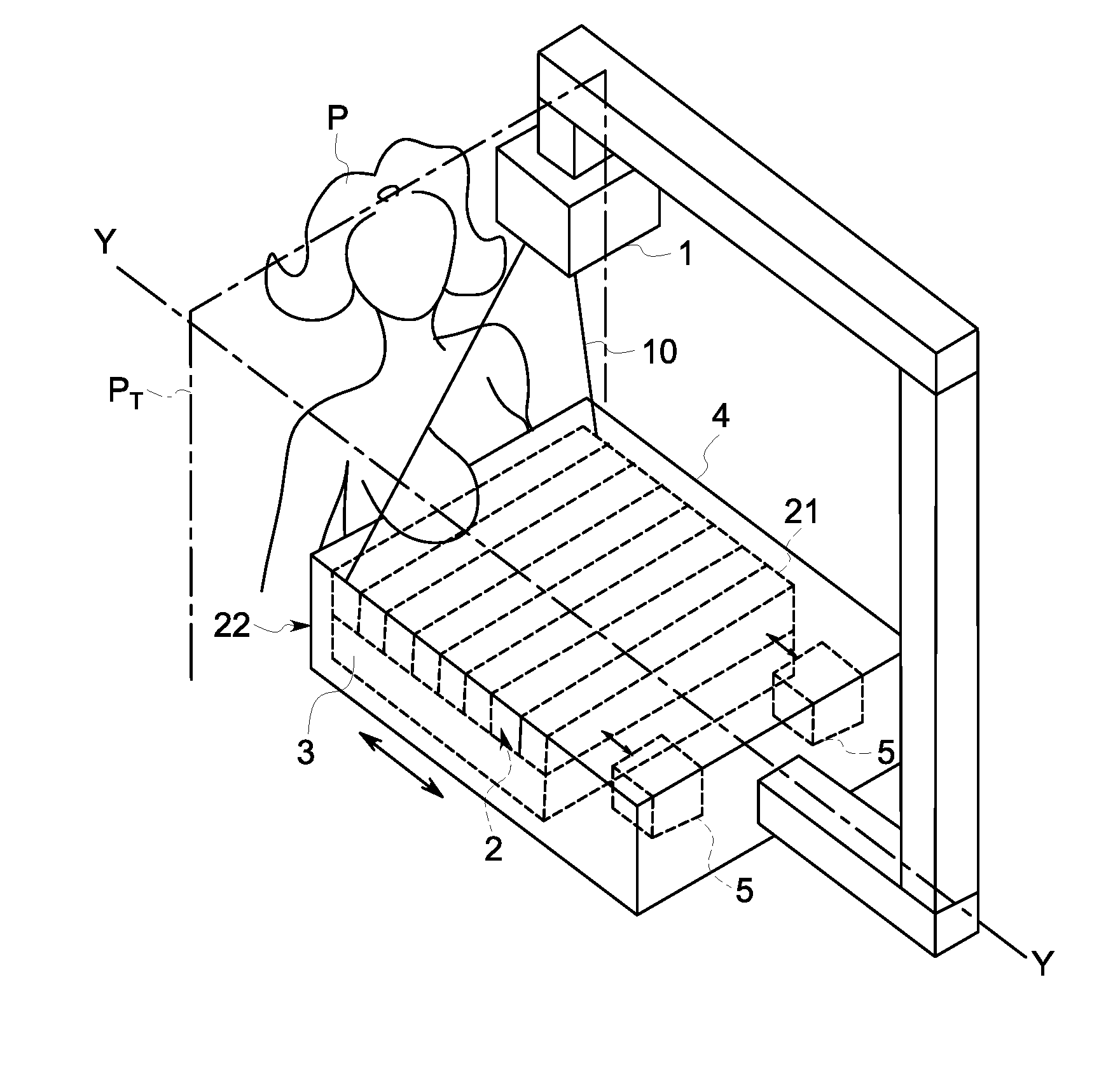
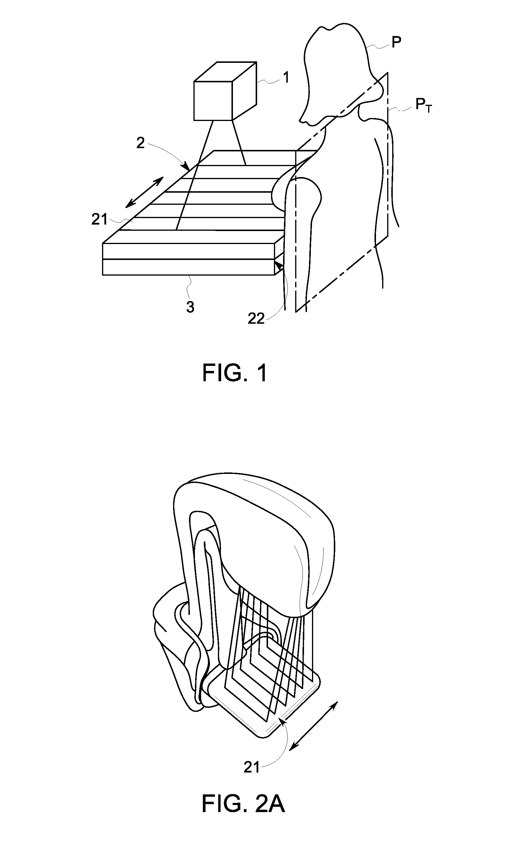
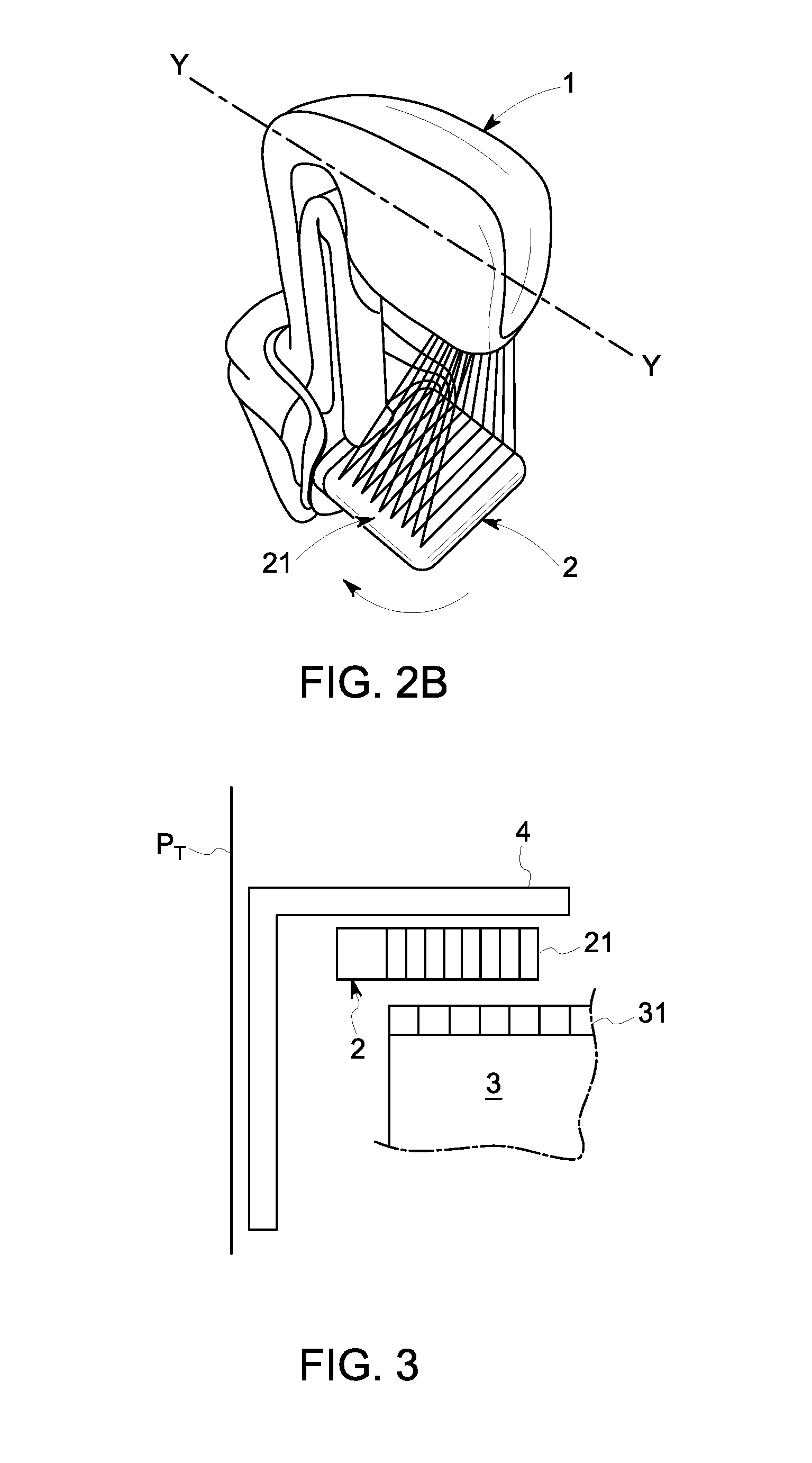
[0034]In reference to FIG. 4, a mammograph is illustrated comprising a radiation source 1, for example of X-ray type, emitting radiation 10 designed to illuminate the breast of a patient P of whom images are to be taken during a pause time T. The radiation transmitted then reaches a detector 3 made up of a network of sensors 31 (Shown in FIG. 3) distributed periodically with a pitch pd of the detector, of the order of 20 to 200 μm.

[0035]An anti-scattering grid 2 is interposed between the source 1 and the detector 3, more precisely between the breast of the patient P and the detector 3, so as to stop radiation scattered by the breast of the patient P not coming directly from the source 1.

[0036]This anti-scattering grid 2 is placed immediately above the detector 3, and is protected by means of a cover 4. This cover also forms a support for the breast of the patient to be examined.

[0037]The grid 2 comprises alternating radio-opaque strips 21, for example constituted by metal, and radio...


PUM

PropertyMeasurementUnit
displacementaaaaaaaaaa
distanceaaaaaaaaaa
movementaaaaaaaaaa

Abstract

A process for deploying an anti-scattering grid in a mammograph is provided. The mammograph comprises a radiation source configured to emit radiation for taking mammographic images of a patient, a radiation detector comprising a network of sensors arranged periodically with a first pitch, and an anti-scattering grid arranged between the source and the detector, the anti-scattering grid comprising radiation adsorbing strips arranged parallel to each other and distributed periodically with a second pitch. The process comprises: displacing the anti-scattering grid relative to the detector or displacing the detector relative to the anti-scattering grid during emission of radiation; adapting the second pitch to the first pitch, wherein displacement is perpendicular to the direction of the strips of the anti-scattering grid, the strips being arranged parallel to a side of the anti-scattering grid positioned against the patient, and altering the positions of the return points between successive periods of the displacement motion.

Description

CROSS-REFERENCE TO RELATED APPLICATIONS[0001]This application is a continuation-in-part of co-pending U.S. patent application Ser. No. 13 / 329,356, filed Dec. 19, 2011, which claims priority to French Patent Application Serial No. 1061334, filed Dec. 29, 2010, now French Patent No. 1061334. This application further claims priority to French Patent Application Serial No. 1651669, filed Feb. 29, 2016. All of the patent applications and patents listed above are hereby incorporated by reference in their respective entireties.BACKGROUND[0002]The present disclosure is generally related to the field of medical imaging, and more particularly the field of radiography. Embodiments of the present invention relate to the field of the deploying anti-scattering grids used to improve radiographic images by filtering the photons scattered by the organ under study, and keeping only the photons emitted by the source. Embodiments of the present invention can be utilised within the scope of mammography,...

Claims


Application Information

Patent Timeline
Patent Type & Authority Applications(United States)
IPC IPC(8): A61B6/00
CPCA61B6/502A61B6/4291A61B6/5252Y10T29/49826
Inventor AUCLAIR, COLINMARTINEZ FERREIRA, CARLOSKLAUSZ, REMY ANDRESOUCHAY, HENRICISARUK, MATHIAS
Owner GENERAL ELECTRIC CO
Why Eureka
Try Eureka