Filter diagnostics and prognostics

a filter and diagnostic technology, applied in the field of lubricant filters, can solve the problems of unfulfilled replacement of filters, unsatisfactory pressure drop across filters measured during these conditions, etc., and achieve the effect of reducing the cost and hazardous waste associated with excessively early filter replacement and reducing the cost of replacemen

Active Publication Date: 2016-07-21
FORD GLOBAL TECH LLC
View PDF8 Cites 20 Cited by
  • Summary
  • Abstract
  • Description
  • Claims
  • Application Information

AI Technical Summary

Benefits of technology

[0009]In this way, pressure differentials across a lubricant filter may be accurately correlated to nominal or degraded filter conditions, which may reduce excessively early filter replacement, in turn reducing costs and hazardous waste issues associated with filter replacement. Thus, the technical result is achieved by these actions.

Problems solved by technology

As such, pressure drops across the filter measured during these conditions are not fully indicative of filter clogging.
Use of filter pressure drops during these conditions may lead to inaccurate identification of filter clogging, which may prompt unnecessary replacement of the filter.

Method used


Image

  • Filter diagnostics and prognostics
  • Filter diagnostics and prognostics
  • Filter diagnostics and prognostics

Examples


Embodiment Construction

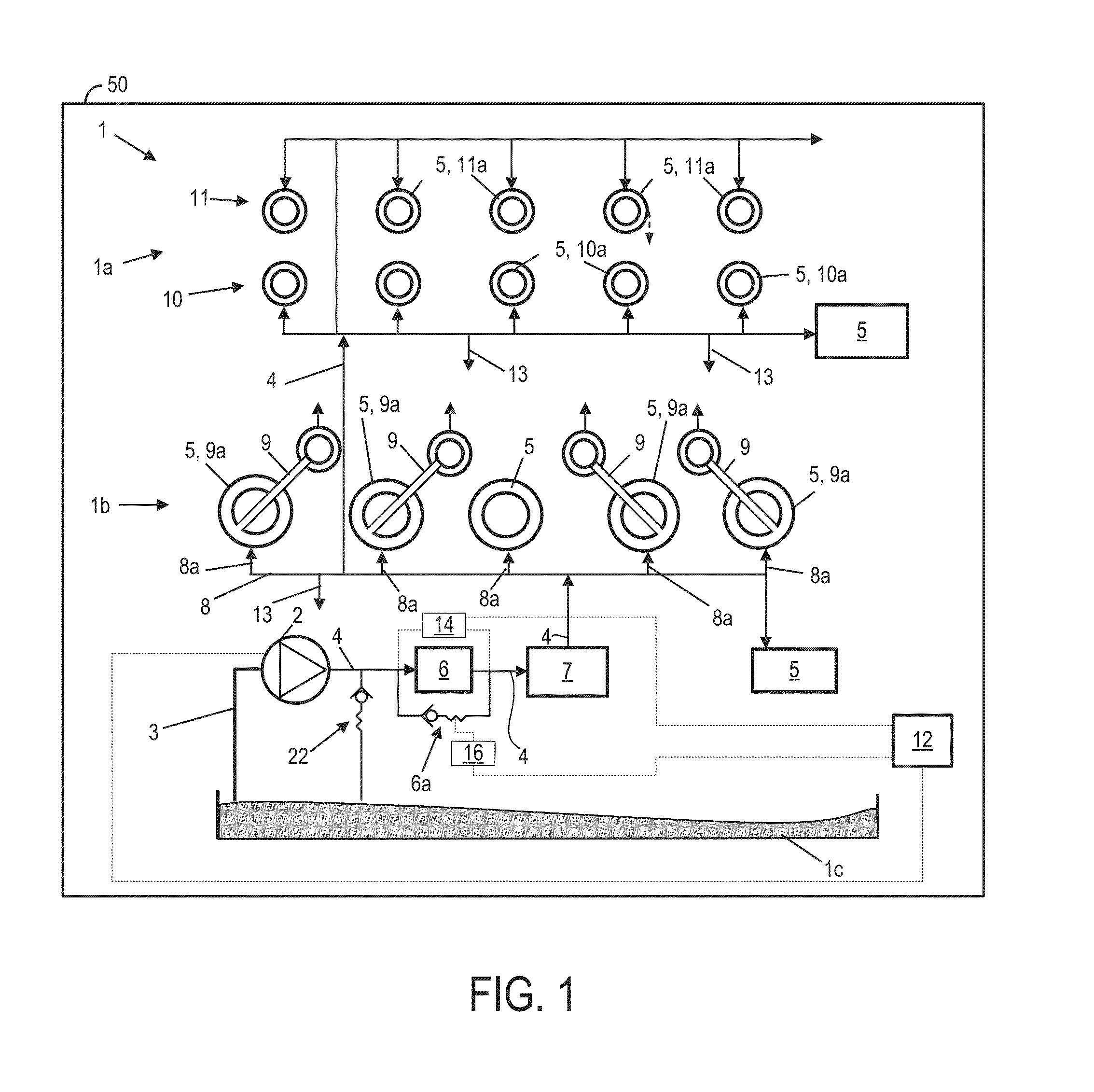
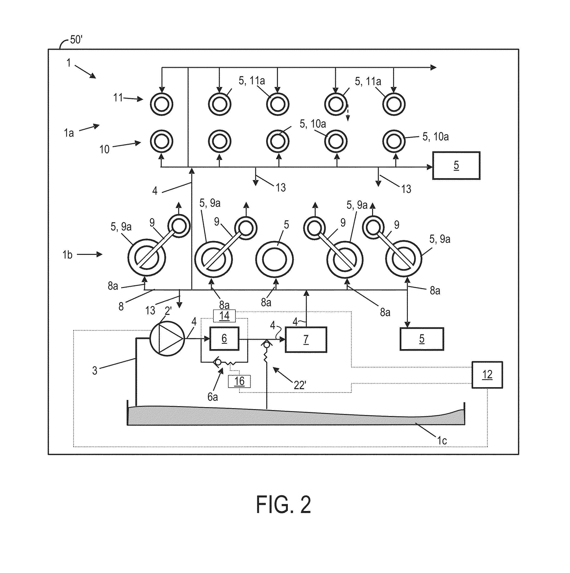
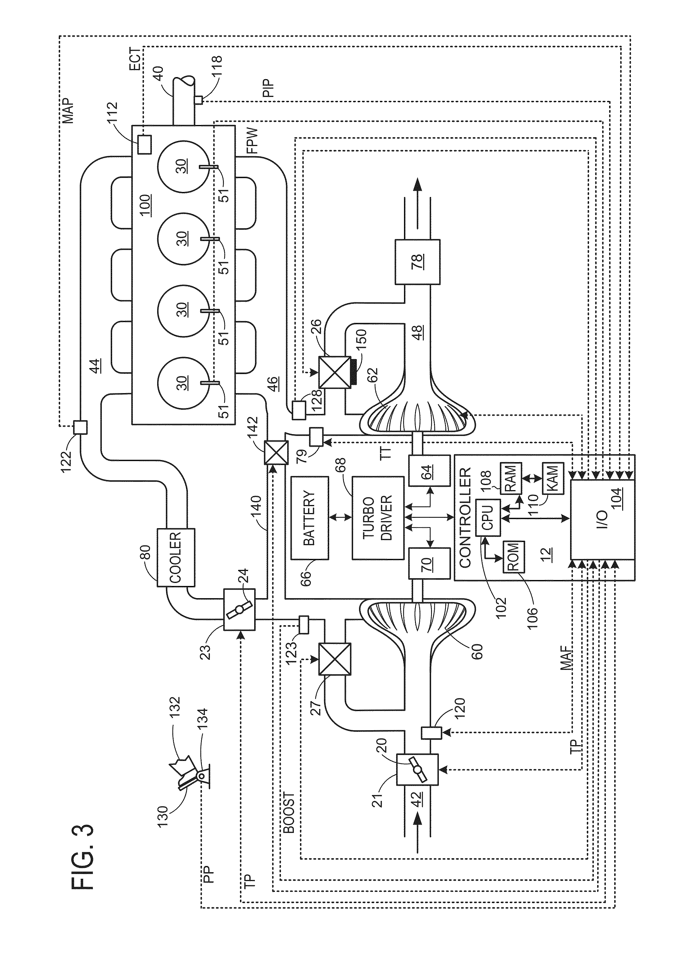
[0017]Various systems and methods are provided for a lubricant filter. In one example, a method for a lubricant filter comprises indicating a condition of the filter based on a difference between a measured pressure differential and an expected pressure differential during select conditions in which all lubricant pumped by a pump upstream of the filter flows into the filter. FIG. 1 shows an example oil circuit of an internal combustion engine, FIG. 2 shows another example oil circuit of an internal combustion engine, FIG. 3 is a schematic diagram showing an example engine, FIGS. 4A-B show a flowchart illustrating a diagnostic routine for a filter in an oil circuit, and FIG. 5 shows a flowchart illustrating a prognostic routine for a filter in an oil circuit. The engine of FIG. 3 also includes a controller configured to carry out the methods depicted in FIGS. 4A-5.

[0018]FIG. 1 schematically shows an example oil circuit 1 of an internal combustion engine 50. Details regarding an examp...


PUM

PropertyMeasurementUnit
thresholdaaaaaaaaaa
pressureaaaaaaaaaa
flow rateaaaaaaaaaa

Abstract

Various systems and methods are provided for a lubricant filter. In one example, a method for a lubricant filter comprises indicating a condition of the filter based on a difference between a measured pressure differential and an expected pressure differential during select conditions in which all lubricant pumped by a pump upstream of the filter flows into the filter.

Description

FIELD[0001]The field of the disclosure relates to lubricant filters.BACKGROUND AND SUMMARY[0002]Lubrication systems are used in internal combustion engines to lubricate and reduce friction within moving components in the engine, thereby increasing the operational life of the components and the engine. For example, pistons, crankshafts, bearings, etc., may be lubricated with oil by a lubrication circuit provided in an engine. The lubrication circuit may include a filter configured to reduce particulates from lubricant that may otherwise interfere with component lubrication. As the filter ages, particulates accumulate therein, eventually reaching a prevalence at which replacement of the filter is recommended.[0003]U.S. Pat. No. 6,553,290 discloses methods of identifying clogging in a lubricant or fluid filter. Specifically, clogging in an engine oil filter is detected by measuring the pressure drop across the filter.[0004]The inventors herein have recognized an issue with the approach...

Claims


Application Information

Patent Timeline
Patent Type & Authority Applications(United States)
IPC IPC(8): B01D29/60
CPCB01D29/606F01M1/10F01M1/18F01M2001/1092F01M1/16F01M11/10F16N2250/04G01M99/00B01D35/143B01D35/1435B01D35/147B01D35/1475
Inventor PURSIFULL, ROSS DYKSTRA
Owner FORD GLOBAL TECH LLC
Why Eureka
Try Eureka