Supercharge Your Innovation With Domain-Expert AI Agents!

Hair clipping device

Active Publication Date: 2016-07-21
KONINKLJIJKE PHILIPS NV
View PDF9 Cites 8 Cited by
  • Summary
  • Abstract
  • Description
  • Claims
  • Application Information

AI Technical Summary

Benefits of technology

The technical effects of this patent are to prevent accumulation of cut hairs between the housing of the hair clipping device and a comb attachment, to increase the visibility of the tips of the cutting assembly for the user, and to minimize the amount of hair that can be trapped under the comb attachment to prevent unwanted clogging.

Problems solved by technology

However, always having to replace the comb attachment by a different one when the haircut length shall be changed might be cumbersome for the user, as this is not only time consuming, but the user also has to store a plurality of differently sized comb attachments.
Therefore, a lot of prior art hair clipping devices use only one comb attachment that is adjustable in different positions relative to the hair clipper housing.
One of the major problems that arises when using hair clippers in combination with a comb attachment is the so-called clogging effect.
This clogging effect arises for stationary combs as well as for adjustable / movable combs.
The clogging effect results from an accumulation of already cut hairs which get trapped and stuck in between the housing and the comb teeth.
Once hairs are entangled in between the housing and the comb teeth, they start collecting more and more cut hairs which finally causes a built-up of already cut hairs and is perceived by the consumer as clogging.
This of course hampers a precise haircut and might even lead to a blockage that jams and / or damages the cutting assembly.

Method used


Image

  • Hair clipping device
  • Hair clipping device
  • Hair clipping device

Examples


first embodiment

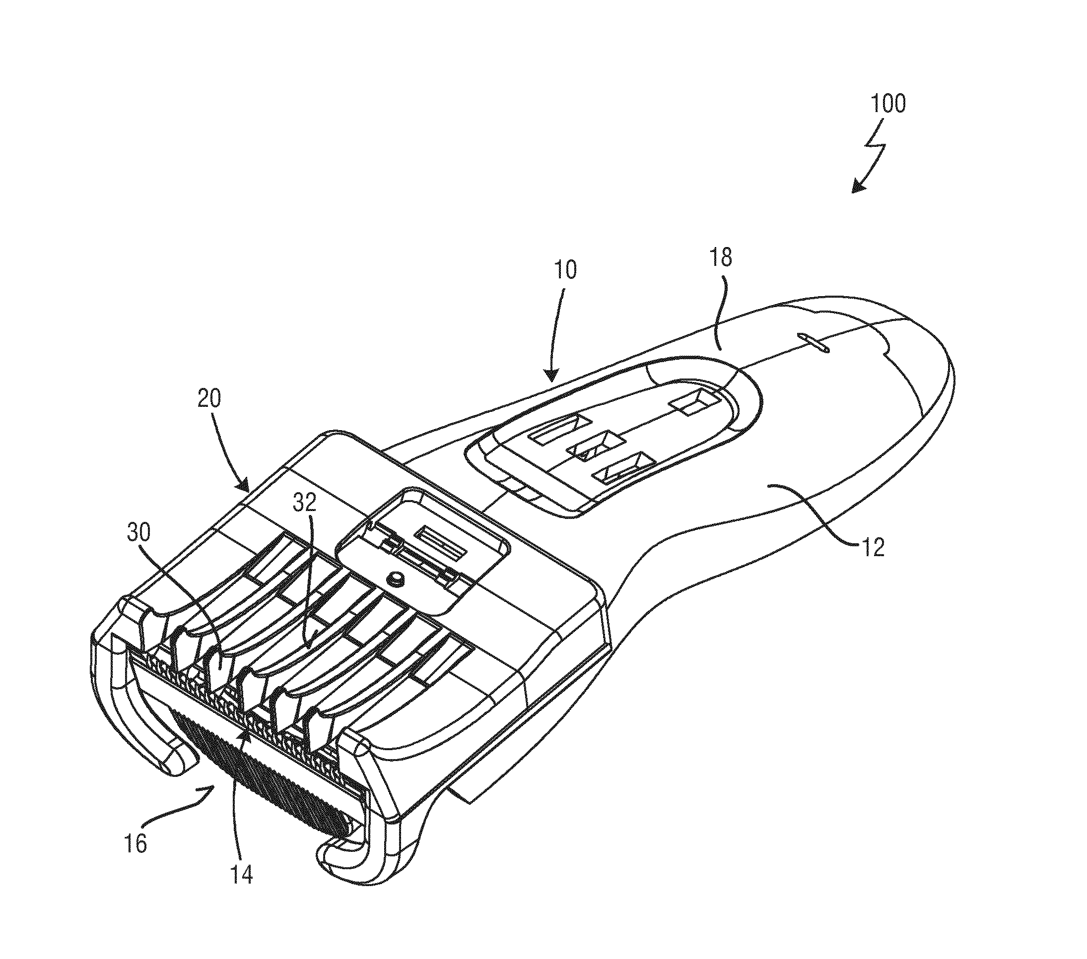
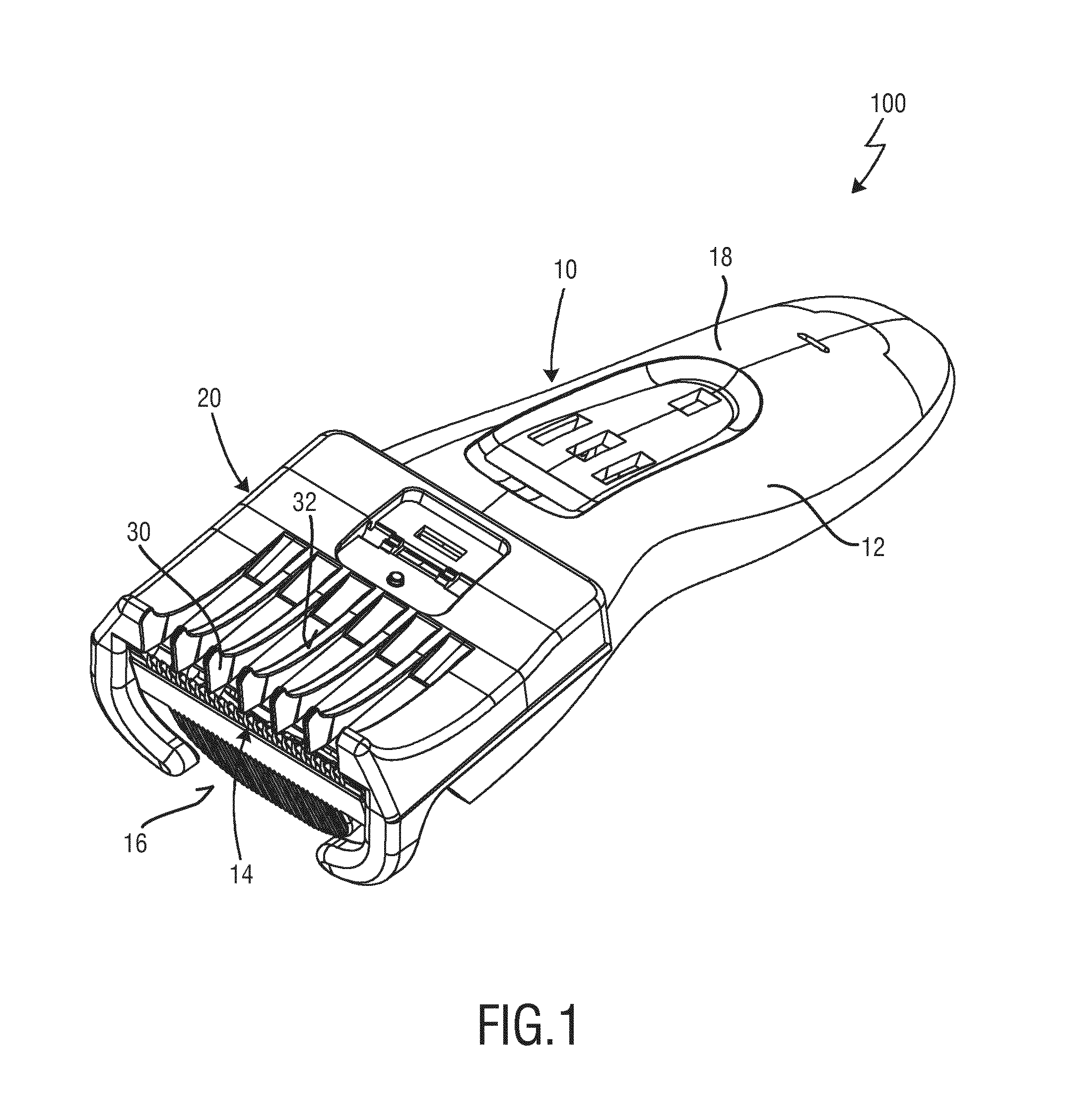
[0051]FIGS. 1 and 2 show the hair clipping device according to the present invention. The hair clipping device is therein in its entirety denoted with reference numeral 100.

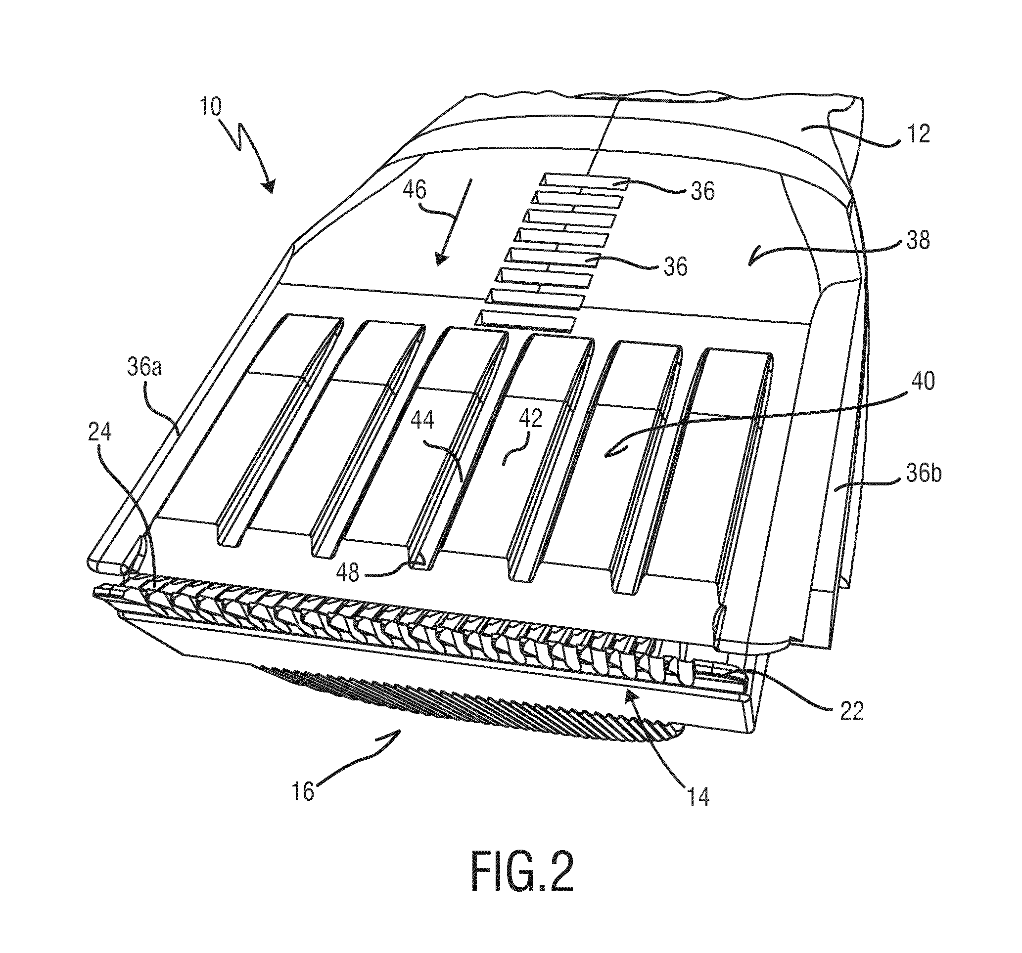
[0052]The hair clipping device 100 comprises a hair clipper 10 (also denoted as hair clipping unit 10) as well as a comb attachment 20 that is releasably attachable to the hair clipper 10. FIG. 1 shows the hair clipping device 100 with the comb 20 attached to the hair clipper 10, whereas FIG. 2 shows an enlarged view of a front end of the hair clipper 10 without comb 20 attached thereto.

[0053]The hair clipper 10 comprises a housing 12 in which all remaining parts are usually integrated and to which the comb 20 may be attached. The housing 12 also serves as a holder for a cutting assembly 14. This cutting assembly 14 may be releasably fixed to a distal end 16 of the housing 12. The cutting assembly 14 may, however, also be permanently fixed to the distal end 16 of the housing 12. The housing 12 is usually realized...

second embodiment

[0078]The gist of the second embodiment shown in FIGS. 5 and 6 is now to fill this cut out area 60 with the ribs 42′ of the corrugated surface 40′, wherein the ribs 42′ having approximately the same height as the cut out area 60. The upper surface or apex 56 of the ribs 42′ is then on the same level with the tips 58 of the cutting blades 22, 24. The recesses 44′ are, however, recessed with respect thereto, so that the front of the cutting assembly 14 is still visible to the user.

[0079]Furthermore, it shall be noted that the ribs 42, 42′ and the recesses 44, 44′ can have a variety of different cross-sections without departing from the scope of the present invention. The ribs 42, 42′ and the recesses 44, 44′ do not necessarily have to have a rectangular cross-section. As shown in FIGS. 8A-8D the ribs 42, 42′ may, for example, also have a step-shaped cross-section (as shown in FIG. 8A), a round cross-section (as shown in FIG. 8B), a triangular cross-section (as shown in FIG. 8C) or a q...


PUM


Abstract

The present invention relates to a hair clipping device (100) comprising: a housing (12), a cutting assembly (14) which is arranged on a distal end (16) of said housing (12) and comprises a stationary cutting blade (22) and a moveable cutting blade (24), and a comb attachment (20) which is releasably attachable to the housing (12) and comprises a plurality of comb teeth (30). A front side (38) of the housing (12) that runs transverse to the distal end (16) and the cutting assembly (14) comprises a corrugated surface (40, 40′) with a plurality of adjacent ribs (42, 42′) and recesses (44, 44′) running parallel to each other. The backside (34) of the comb teeth (30) contacts said corrugated surface (40, 40′) when the comb attachment (20) is attached to the housing (12).

Description

FIELD OF THE INVENTION[0001]The present invention relates to a hair clipping device, in particular to a hair clipping device with a comb attachment that is adapted to variably adjust the length of the haircut.BACKGROUND OF THE INVENTION[0002]Electric haircutting appliances are generally known and include trimmers, clippers and shavers whether powered by main supplied electricity or batteries. Such devices are generally used to trim body hair, in particular facial and head hair to allow a person to have a well-groomed appearance.[0003]Commonly, conventional devices for cutting hair comprises a main body forming an elongated housing having a front or cutting end (also referred to as distal end) and an opposite handle end. A cutting assembly is disposed at the distal end. The cutting assembly usually comprises a stationary cutting blade and a movable cutting blade which moves in a reciprocal manner against the stationary cutting blade. The cutting assembly is usually fixed in a single ...

Claims


Application Information

Patent Timeline
IPC IPC(8): B26B19/20B26B19/06
CPCB26B19/06B26B19/20
Inventor TUIJP, BRAMNAB, MARTIJN FRANS JOHANHOEXUM, EVERHARDUS JOHANNESTIJSSEN, REINIER ALEXANDER
Owner KONINKLJIJKE PHILIPS NV
Features
  • R&D
  • Intellectual Property
  • Life Sciences
  • Materials
  • Tech Scout
  • Unparalleled Data Quality
  • Higher Quality Content
  • 60% Fewer Hallucinations
Learn More