Pressure sensor, method of manufacturing pressure sensor, altimeter, electronic apparatus, and moving object

a manufacturing method and pressure sensor technology, applied in the direction of fluid pressure measurement, fluid pressure measurement by electric/magnetic elements, instruments, etc., can solve the problems of air bubbles easily occurring and the accuracy of pressure detection deteriorating, and achieve the effect of high reliability

Inactive Publication Date: 2016-07-21
SEIKO EPSON CORP
View PDF5 Cites 23 Cited by
  • Summary
  • Abstract
  • Description
  • Claims
  • Application Information

AI Technical Summary

Benefits of technology

[0007]An advantage of some aspects of the invention is to provide a pressure sensor in which air bubbles do not easily come into contact with a pressure receiving surface of the diaphragm and deterioration in pressure detection accuracy can be reduced, a method of manufacturing the pressure sensor, and an altimeter, an electronic apparatus, and a moving object including the pressure sensor.
[0026]With this configuration, it is possible to obtain the pressure sensor in which air bubbles less easily come into contact with the pressure receiving surface of the diaphragm, a stress balance on both sides (the diaphragm side and the opposite side of the diaphragm) of the pressure reference chamber less easily changes, and deterioration in pressure detection accuracy can be reduced.Application Example 10
[0034]With this configuration, it is possible to obtain the pressure sensor in which air bubbles less easily come into contact with the pressure receiving surface of the diaphragm, a stress balance on both sides (the diaphragm side and the opposite side of the diaphragm) of the pressure reference chamber less easily changes, and deterioration in pressure detection accuracy can be reduced.Application Example 14
[0042]With this configuration, it is possible to obtain the moving object having high reliability.

Problems solved by technology

However, in the pressure sensor having such a configuration, for example, air bubbles easily occur when the inert liquid is filled in the package.
If the air bubbles come into contact with a pressure receiving surface of the diaphragm, pressure detection accuracy is deteriorated.

Method used


Image

  • Pressure sensor, method of manufacturing pressure sensor, altimeter, electronic apparatus, and moving object
  • Pressure sensor, method of manufacturing pressure sensor, altimeter, electronic apparatus, and moving object
  • Pressure sensor, method of manufacturing pressure sensor, altimeter, electronic apparatus, and moving object

Examples


first embodiment

[0065]First, a pressure sensor according to a first embodiment of the invention is explained.

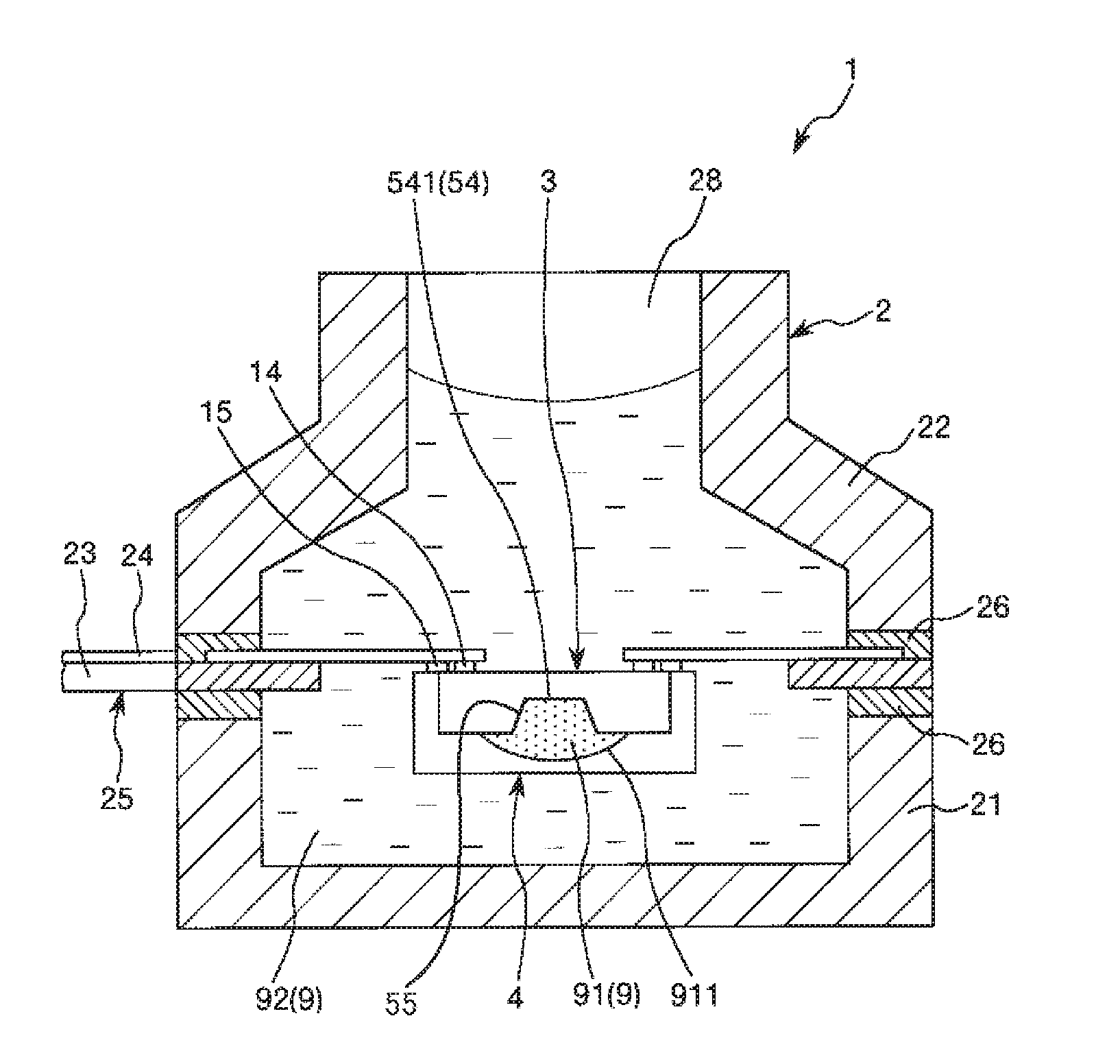
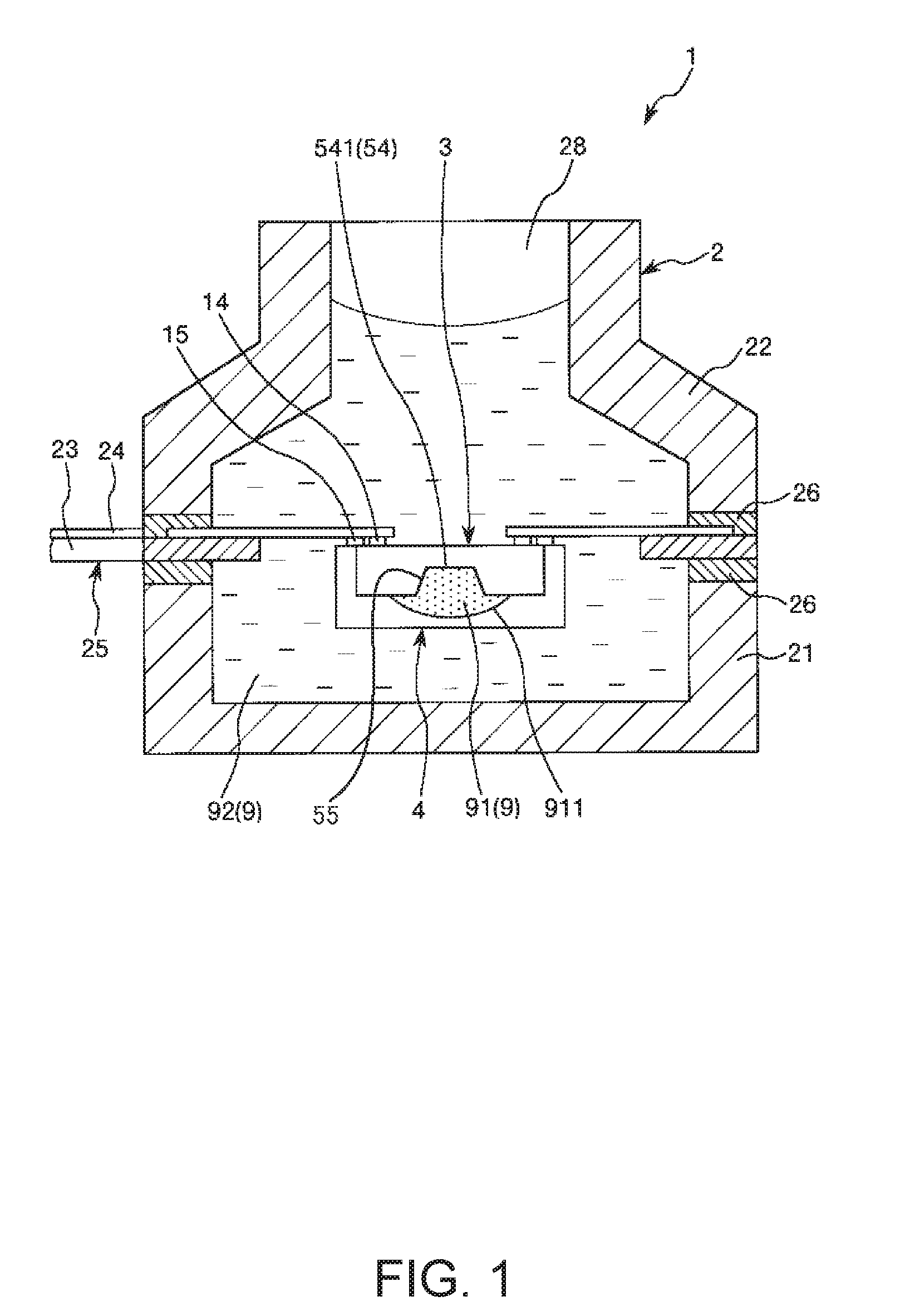
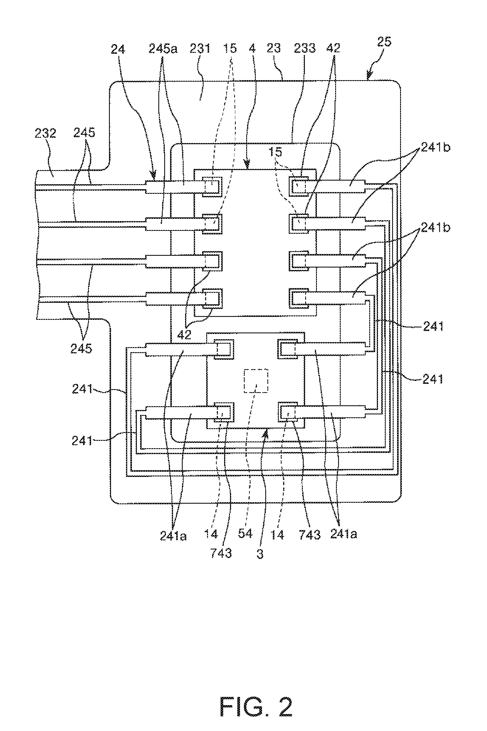
[0066]FIG. 1 is a sectional view of the pressure sensor according to the first embodiment. FIG. 2 is a plan view of a flexible wiring board included in the pressure sensor shown in FIG. 1. FIG. 3 is a sectional view of a pressure sensor element included in the pressure sensor shown in FIG. 1. FIG. 4 is a plan view showing a pressure sensor section included in the pressure sensor element shown in FIG. 3. FIG. 5 is a diagram showing a bridge circuit including the pressure sensor section shown in FIG. 4. FIGS. 6A to 6C and FIGS. 7A and 7B are sectional views for explaining a method of manufacturing the pressure sensor shown in FIG. 1. Note that, in the following explanation, an upper side in FIG. 3 is referred to as “upper” as well and a lower side is referred to as “lower” as well.

[0067]The pressure sensor 1 shown in FIG. 1 includes a pressure sensor element 3, an IC chip 4 electrically connec...

second embodiment

[0112]FIG. 8 is a sectional view of a pressure sensor according to a second embodiment of the invention.

[0113]The pressure sensor according to the second embodiment is explained below. Differences from the first embodiment are mainly explained. Explanation of similarities is omitted.

[0114]The pressure sensor 1 in the second embodiment is the same as the pressure sensor 1 in the first embodiment except that the direction of a pressure sensor element in a package is different.

[0115]As shown in FIG. 8, in the pressure sensor 1 in this embodiment, the pressure sensor element 3 is housed in the package 2 in a posture in which the pressure receiving surface 541 of the diaphragm 54 is directed to the opening side of the package 2. By adopting such disposition, the pressure receiving surface 541 can be set close to the opening of the package 2. Therefore, pressure applied to the pressure sensor 1 more efficiently acts on the pressure receiving surface 541.

[0116]According to the second embod...

third embodiment

[0117]FIG. 9 is a sectional view of a pressure sensor according to a third embodiment of the invention.

[0118]The pressure sensor in the third embodiment is explained below. Differences from the embodiments explained above are mainly explained. Explanation of similarities is omitted.

[0119]The pressure sensor 1 in the third embodiment is the same as the pressure sensor 1 in the first embodiment except that disposition of a pressure sensor element and an IC chip in a package is different.

[0120]As shown in FIG. 9, in the pressure sensor 1 in this embodiment, the pressure sensor element 3 and the IC chip 4 are disposed to overlap each other in the thickness direction. Consequently, it is possible to suppress a planar spread of the pressure sensor 1. It is possible to attain a reduction in the size of the pressure sensor 1. Note that, in this embodiment, the pressure sensor element 3 is disposed on the upper side of the IC chip 4. Conversely, the pressure sensor element 3 may be disposed ...


PUM

PropertyMeasurementUnit
pressureaaaaaaaaaa
pressure detection accuracyaaaaaaaaaa
curing rateaaaaaaaaaa

Abstract

A pressure sensor includes a pressure sensor element having a pressure receiving surface and a filler (a resin section) disposed to surround the pressure sensor element. The filler includes a first portion that is at least in contact with the pressure receiving surface and a second portion located around the first portion and surrounding the first portion and the pressure sensor element. A curing rate of the first portion is higher than a curing rate of the second portion.

Description

CROSS REFERENCE[0001]This application claims benefit of Japanese Applications JP 2015-008246, filed on Jan. 20, 2015 and JP 2015-008360, filed on Jan. 20, 2015. The disclosures of the prior applications are hereby incorporated by reference herein in their entirety.BACKGROUND[0002]1. Technical Field[0003]The present invention relates to a pressure sensor, a method of manufacturing the pressure sensor, an altimeter, an electronic apparatus, and a moving object.[0004]2. Related Art[0005]There has be known a pressure sensor including a sensor chip that detects pressure and generates an electric signal corresponding to a detection value of the pressure, a package that houses the sensor chip, and inert liquid that surrounds the sensor chip in the package and propagates the pressure to the sensor chip (see, for example, JP-A-9-126920 (Patent Literature 1)). In the pressure sensor, the sensor chip includes a diaphragm that bends with received pressure and a pressure reference chamber provid...

Claims


Application Information

Patent Timeline
Patent Type & Authority Applications(United States)
IPC IPC(8): G01L9/00G01C5/06
CPCG01C5/06G01L9/0054G01L9/0052G01L9/065G01L19/0069G01L19/0084G01L19/0627G01L19/141H01L2224/10
Inventor NAKAJIMA, SATOSHI
Owner SEIKO EPSON CORP
Why Eureka
Try Eureka