Eureka AIR delivers breakthrough ideas for toughest innovation challenges, trusted by R&D personnel around the world.

Communications system, infrastructure equipment, communication terminal and method

a technology for infrastructure equipment and communication terminals, applied in the field of communication systems, infrastructure equipment and communications terminals for communicating data, can solve the problems of increasing the likelihood of a handover to another infrastructure equipment, incurring increased delay, etc., and achieve the effect of conserving the resources of the wireless access interfa

Active Publication Date: 2016-07-21
SONY CORP
View PDF9 Cites 17 Cited by
  • Summary
  • Abstract
  • Description
  • Claims
  • Application Information

AI Technical Summary

Benefits of technology

The patent text describes a feature for a communication terminal that allows it to quickly exit a reduced power state when the quality of the link to the infrastructure equipment is poor, to reduce the delay in reporting a handover event. This improves the likelihood of a smooth handover to another infrastructure equipment before the link fails, reducing power consumption and network resources. The communication terminal can also increase its monitoring of link quality without fully recovering data from received signals, which allows it to remain in the reduced power state while still monitoring link quality. The infrastructure equipment can adjust the threshold for triggering a handover based on traffic conditions to optimize resource utilization. Hardcoding the threshold helps conserve resources of the wireless access interface.

Problems solved by technology

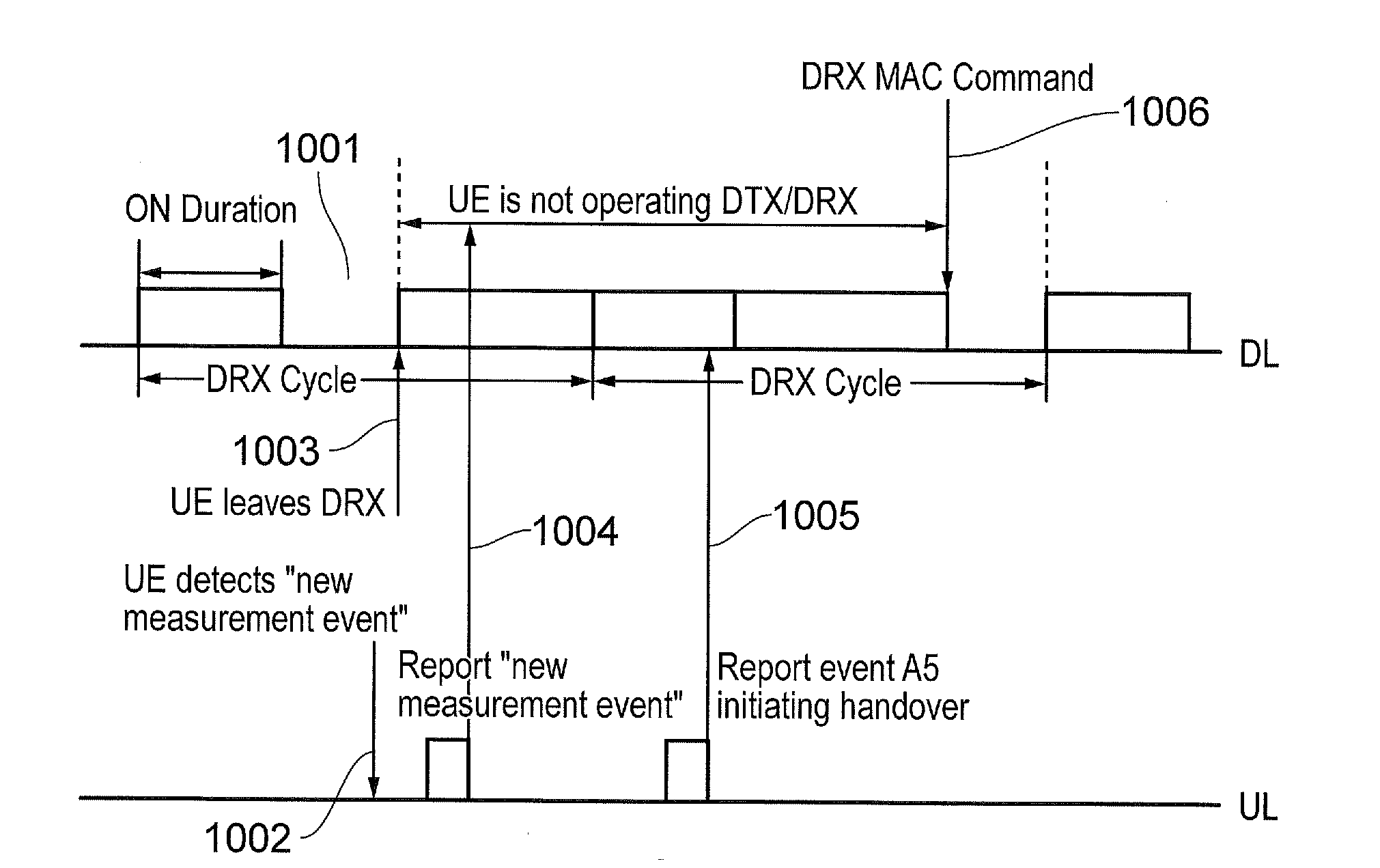
Accordingly, these features increase the likelihood that a handover to another infrastructure equipment can take place before the link with the serving infrastructure equipment fails and a re-connection procedure is required.
Conversely, for a communication terminal which does not exit the reduced power state, it will be required to wait at least a first period after a handover initiating event has occurred to report any event, thus possibly incurring increased delay.

Method used


Image

  • Communications system,  infrastructure equipment, communication terminal and method
  • Communications system,  infrastructure equipment, communication terminal and method
  • Communications system,  infrastructure equipment, communication terminal and method

Examples


Embodiment Construction

Mobile Communications Network

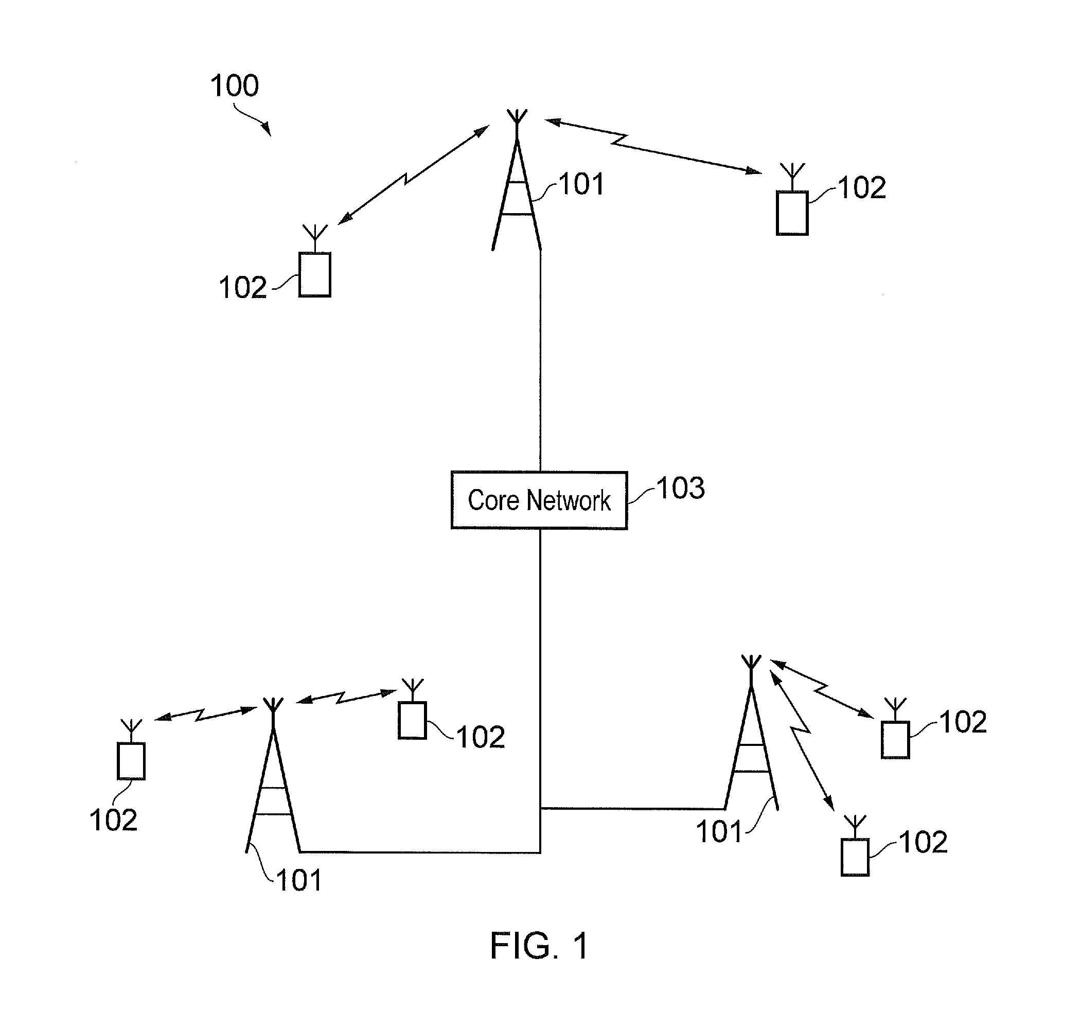
[0032]FIG. 1 provides a schematic diagram of an example mobile communications network 100. The mobile communications network includes infrastructure equipment 101 which is arranged to provide a wireless access interface to communications terminals 102 within a coverage area or cell. Signals representing downlink data are transmitted from the infrastructure equipment and received by the communication terminals via the wireless access interface, and signals representing uplink data are transmitted by the communication terminals and received by the infrastructure equipment via the wireless access interface. The infrastructure equipment may be communicatively linked via a core network to other infrastructure equipment which may in turn be linked to further communications networks. The infrastructure equipment may also be referred to as a base station or an enhanced node B (eNode B) and the communications terminals may be referred to as user equipment (UE), m...


PUM


Abstract

A communications system for communicating data to and from a communication terminal, including infrastructure equipment forming a mobile communications network arranged to transmit and receive signals representing data to and from the communication terminal via a wireless access interface. The communication terminal is configured to transmit and receive signals representing data to / from the infrastructure equipment and to enter a reduced-power state, during which the communication terminal is configured to periodically recover data from the signals received from the infrastructure equipment, to measure a parameter indicating a characteristic of at least some of the signals received from the infrastructure equipment during the reduced power state, and to exit the reduced power state and to transmit a message to the infrastructure equipment, the message requesting resources of the wireless access interface, in dependence upon the measured parameter relative to a predetermined threshold.

Description

FIELD OF THE DISCLOSURE[0001]The present disclosure relates to communications systems, infrastructure equipment and communications terminals for communicating data and methods of communicating data.BACKGROUND OF THE DISCLOSURE[0002]Extending network coverage, reducing power consumption and increasing network capacity and efficiency are some of the technical challenges which affect the design and deployment of mobile communications networks. One approach to reduce the power consumed by a user device and to increase network efficiency is to decrease the time spent transmitting and receiving signals and recovering data from received signals at both user devices and serving base stations. For example, if it is known by a user device that data intended for it is not to be transmitted within a predetermined period of time, the user device is able to cease recovering data from signals received during this period of time, thus reducing power consumption. Likewise, network resources can also...

Claims


Application Information

Patent Timeline
IPC IPC(8): H04W52/02H04W72/08H04W36/30
CPCH04W52/0225H04W72/085H04W36/30H04W36/165H04W52/0229H04W52/0245H04W36/26H04W76/28Y02D30/70H04W36/304H04W72/542
Inventor KAHTAVA, JUSSIRICHARDS, DEREK JOHN
Owner SONY CORP
Why Eureka
Eureka Blog
Learn More