Heat removal structure of aircraft main landing gear bay
a technology for aircraft and landing gear, which is applied in the direction of brake cooling, brake systems, transportation and packaging, etc., can solve the problems of large frictional heat generated by brakes, add to the size of airframes, and add to the space required for installing devices in the main landing gear bays
- Summary
- Abstract
- Description
- Claims
- Application Information
AI Technical Summary
Benefits of technology
Problems solved by technology
Method used
Image

Examples
first embodiment
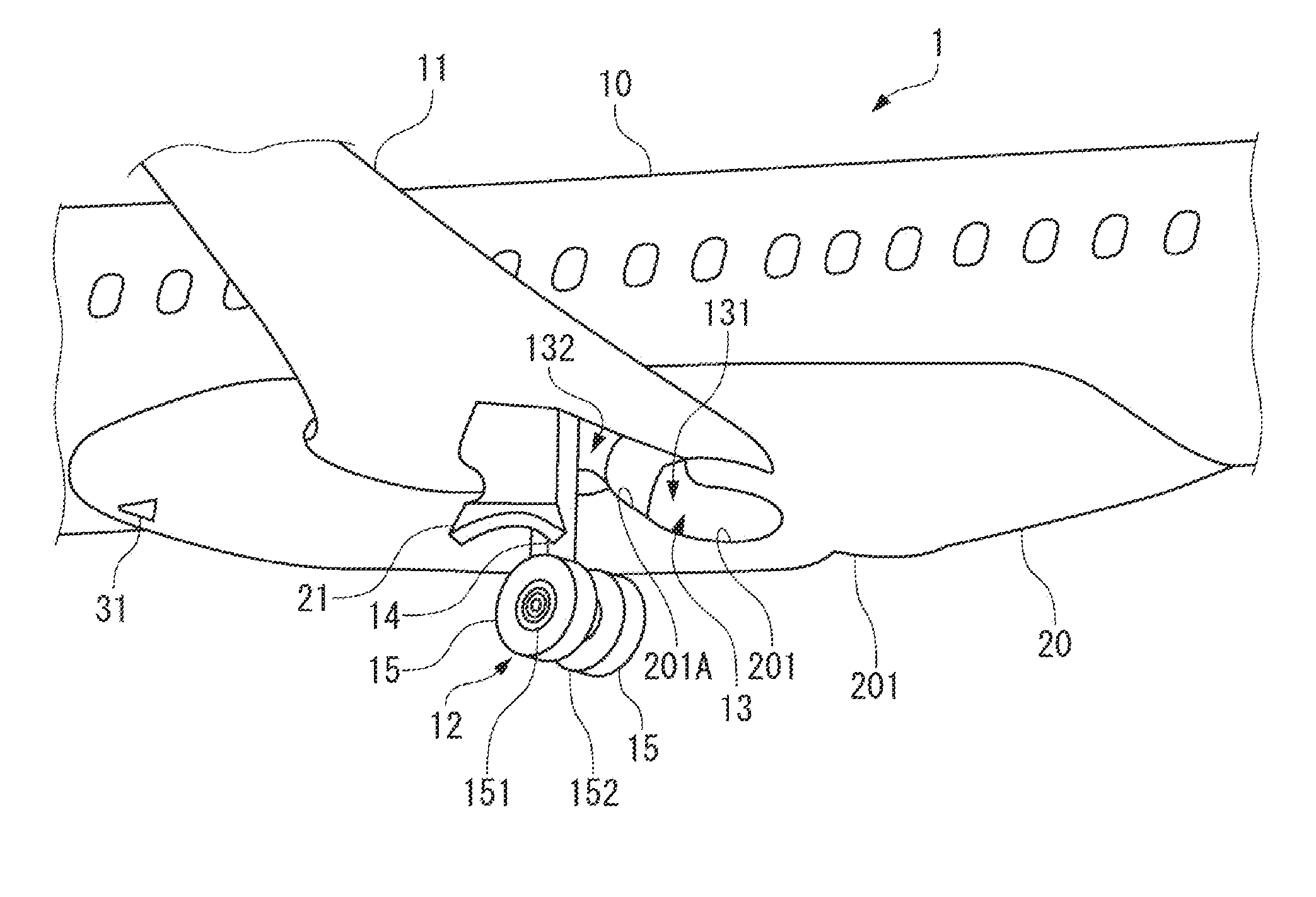
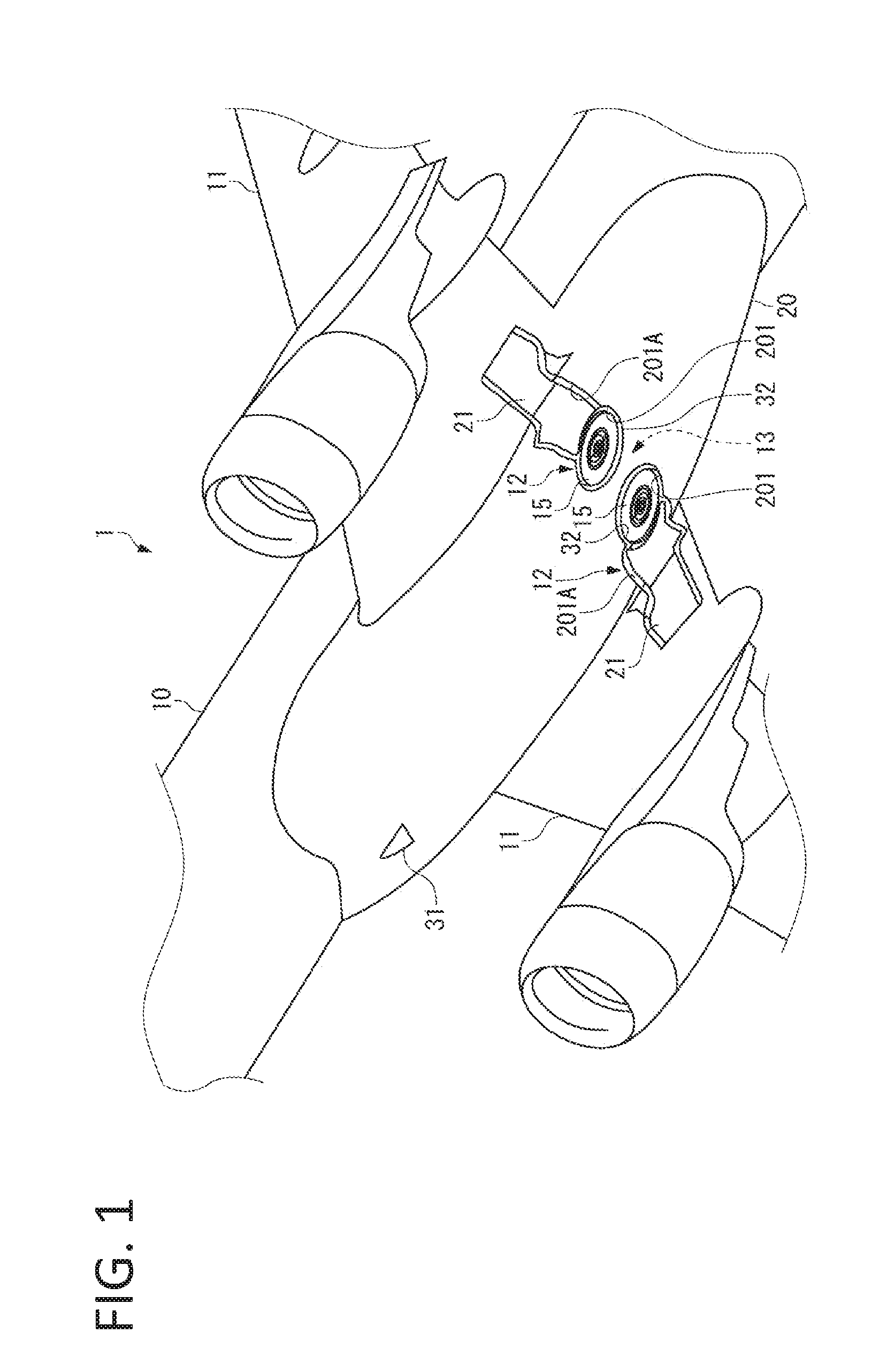
[0039]As shown in FIG. 1, an aircraft 1 of this embodiment includes a fuselage 10 and main wings 11 provided on the left side and the right side of the fuselage 10.
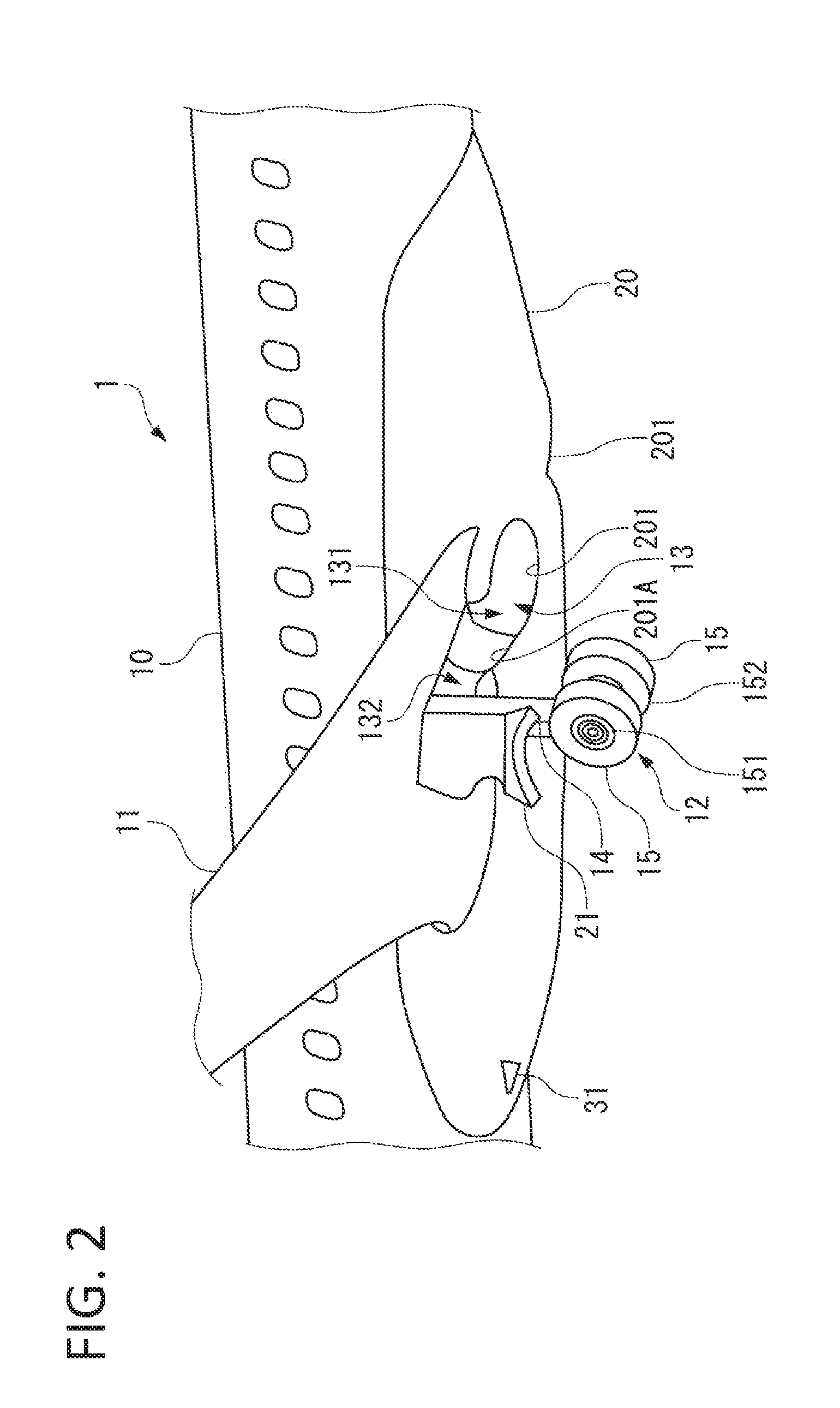
[0040]In the vicinity of a joint part between the fuselage 10 and the left and right main wings 11, 11, the fuselage 10 is equipped with a pair of left and right main landing gears 12, 12 (undercarriage) supporting an airframe, and a main landing gear bay 13 (FIG. 2) into which the main landing gears 12, 12 are retracted.
[0041]As shown in FIG. 2, the main landing gears 12, 12 are deployed downward from the main landing gear bay 13. The right main landing gear 12 is not shown in FIG. 2.
[0042]Each main landing gear 12 includes a pillar 14 supporting the airframe, wheels 15, 15 provided on the pillar 14 and traveling on the ground, and braking devices 16, 16 (FIG. 3) respectively braking the wheels 15, 15.
[0043]The main landing gear 12 is moved up and down by being turned by a hydraulic actuator (not shown) around a base end...
second embodiment
[0084]Next, a second embodiment of the present invention will be described with reference to FIG. 5.
[0085]In the second embodiment, as in the first embodiment, the clearance located in the outer periphery of the wheel 15 exposed from the wheel opening 201 is used for suctioning / discharging air. However, whether the clearance located in the outer periphery of the wheel 15 functions as the outlet port as in the first embodiment, or functions as the inlet port, is determined by the positional and directional relation with another opening leading to external air. Moreover, the inlet port and the outlet port may be reversed as the differential pressures at the inlet port and the outlet port are reversed according to the state of air pressure and airflow etc.
[0086]That is, unlike in the first embodiment in which air is suctioned from the front side and discharged from the rear side, the direction of air suction / discharge is not limited in the second embodiment.
[0087]In the following, diff...
third embodiment
[0095]Next, a third embodiment of the present invention will be described with reference to FIG. 6.
[0096]In the third embodiment, a shutter which can open / close a ventilation port for air suction / discharge will be described.
[0097]The ventilation ports for air suction / discharge of the heat removal structure of the main landing gear bay 13 described in the first embodiment and the second embodiment cause some air resistance to an airflow flowing along the surface of the fairing 20 or the main landing gear door 21. Therefore, providing a shutter which can open / close the ventilation port according to the necessity for heat removal is effective in reducing the air resistance.
[0098]A shutter 50 shown in FIG. 6A is formed in a plate-like shape, and sliding the shutter 50 along guide rails (not shown) provided in the fairing 20 can open / close a ventilation port 51. As long as the ventilation port 51 can be closed, the shape and the dimensions of the shutter 50 are arbitrary.
[0099]The ventil...
PUM
 Abstract
Description
Claims
Application Information
 - R&D
- Intellectual Property
- Life Sciences
- Materials
- Tech Scout
- Unparalleled Data Quality
- Higher Quality Content
- 60% Fewer Hallucinations
Browse by: Latest US Patents, China's latest patents, Technical Efficacy Thesaurus, Application Domain, Technology Topic, Popular Technical Reports.
© 2025 PatSnap. All rights reserved.Legal|Privacy policy|Modern Slavery Act Transparency Statement|Sitemap|About US| Contact US: help@patsnap.com