

Light scanning apparatus
a scanning apparatus and light technology, applied in the direction of electrographic process apparatus, instruments, printing, etc., can solve the problems of difficult identification of reflection surface and image defects, and achieve the effect of preventing image defects and facilitating identification
- Summary
- Abstract
- Description
- Claims
- Application Information
AI Technical Summary
Benefits of technology
Problems solved by technology
Method used
Image

Examples
first embodiment
[0033](Image Forming Apparatus)
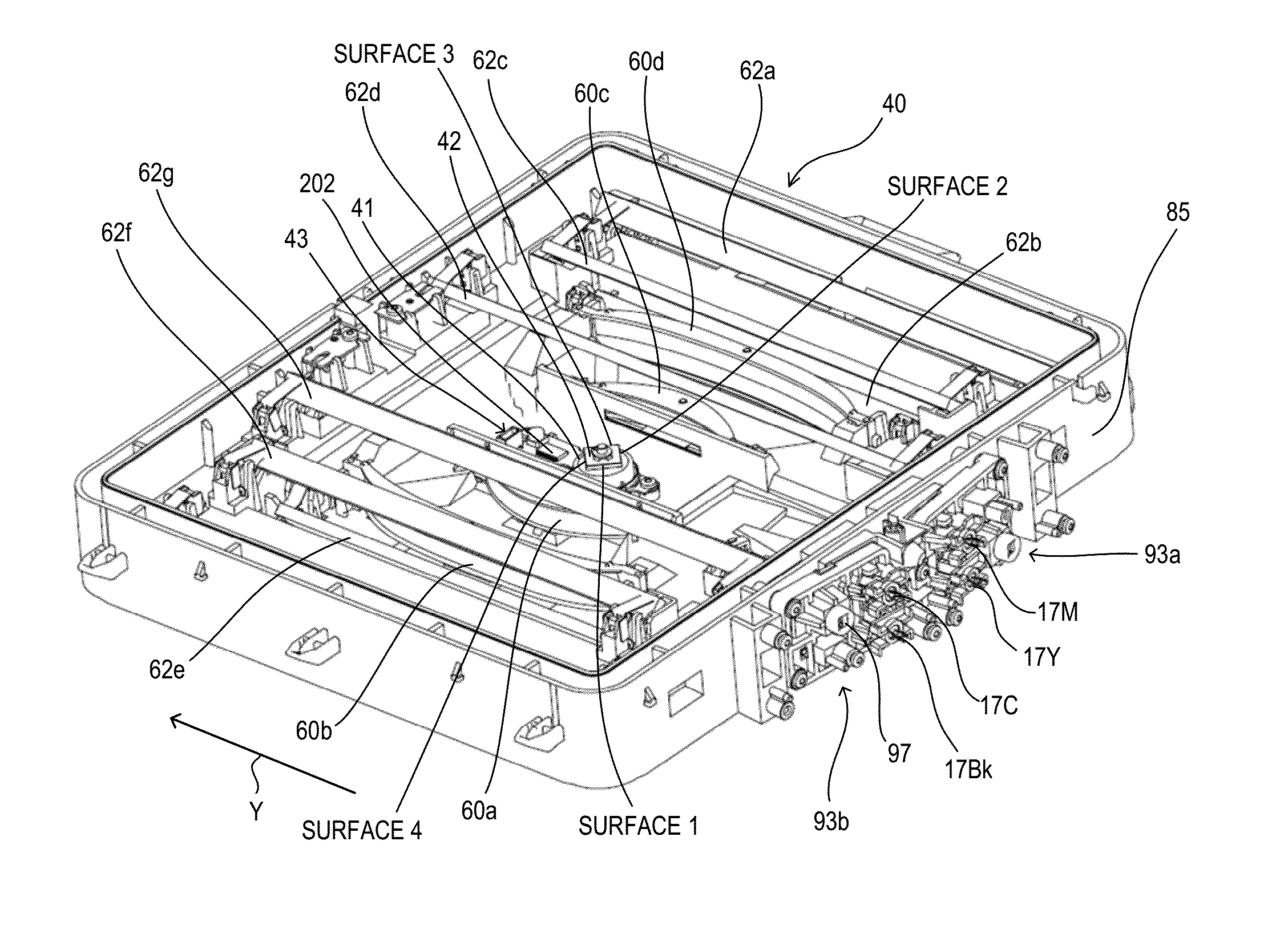
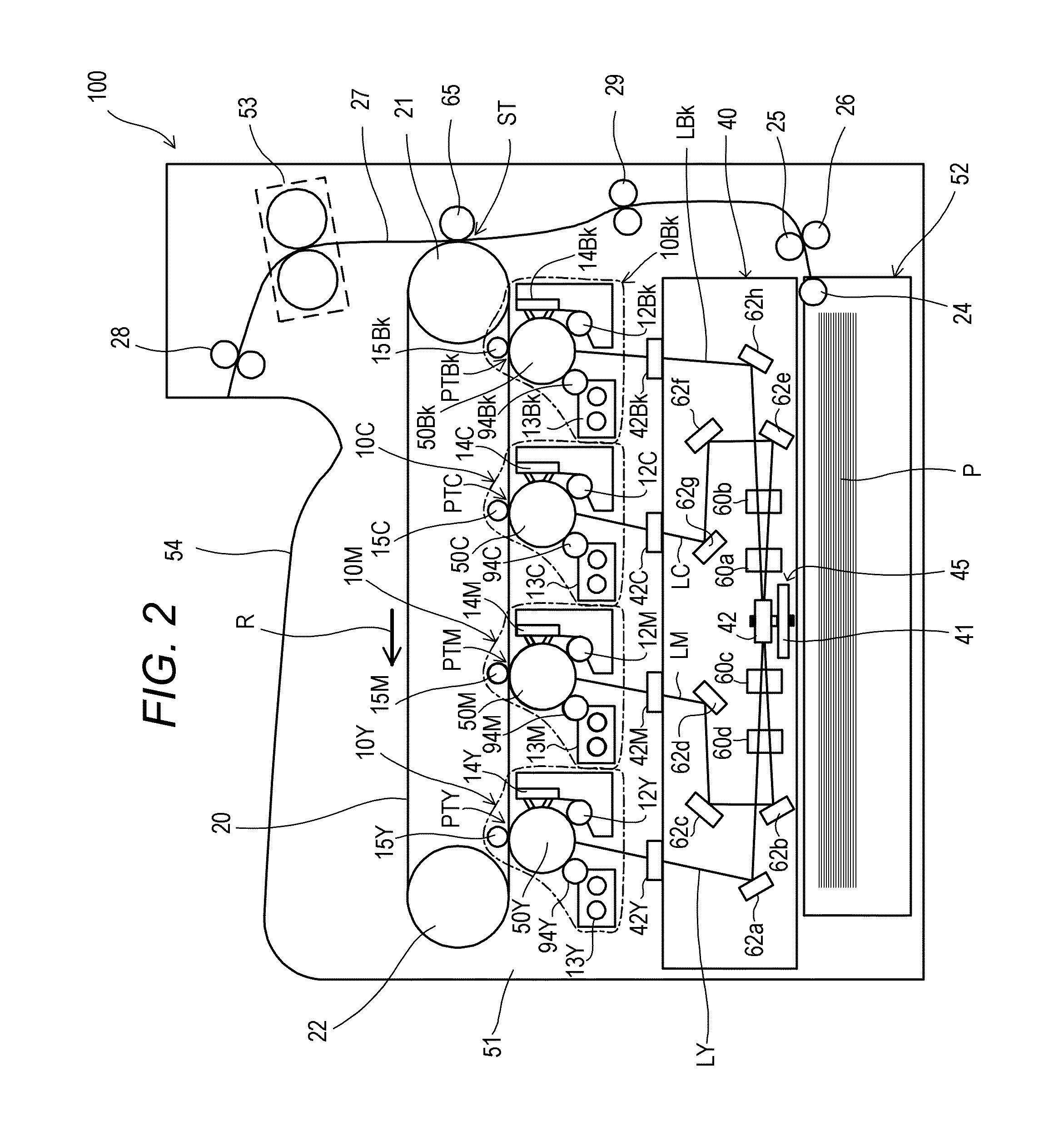
[0034]An electrophotographic image forming apparatus (hereinafter referred to as “image forming apparatus”) 100 according to the embodiment will be described. FIG. 2 is a sectional view of the image forming apparatus 100. As an example of the image forming apparatus 100, a tandem-type color laser beam printer is illustrated. The image forming apparatus 100 is configured to form an image on a recording medium (hereinafter referred to as “sheet”) P using an electrophotographic method. The image forming apparatus 100 includes four image forming portions 10 (10Y, 10M, 10C, 10Bk). The suffixes Y, M, C, and Bk of the reference symbols indicate yellow, magenta, cyan, and black, respectively. In the following description, the suffixes Y, M, C, and Bk may be omitted.
[0035]The image forming portions 10 each include a photosensitive drum serving as an image bearing member (hereinafter referred to as “photosensitive member”) 50 (50Y, 50M, 50C, 50Bk). A process mem...
second embodiment
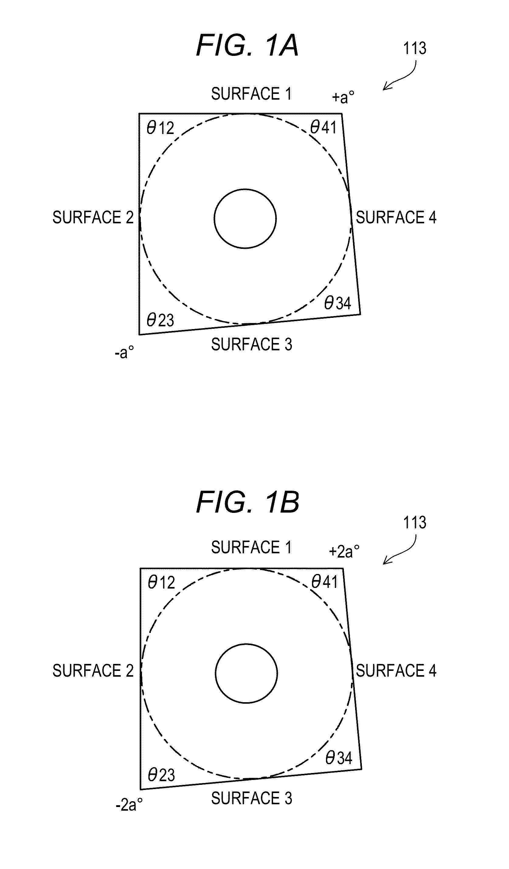
[0156]In the first embodiment, the rotary four-sided polygon mirror 113 is described as an example of the rotary polygon mirror 42. But in a second embodiment, a rotary six-sided polygon mirror will be described as an example of the rotary polygon mirror 42. In the second embodiment, the structure similar to that in the first embodiment is denoted by the same reference symbol, and description thereof is omitted herein. The image forming apparatus 100 and the light scanning apparatus 40 of the second embodiment are similar to those in the first embodiment, and hence description thereof is omitted herein. As described in the first embodiment, when the rotary four-sided polygon mirror is formed in a non-regular four-sided polygon to cause a difference in BD signal period, the only pattern that creates the periodicity is (2 surfaces)×(2 periods). Further, the configuration for reliably avoiding the possibility to cause (2 surfaces)×(2 periods) has a strong tolerance against a manufactur...
third embodiment
[0183]Now, a third embodiment of the present invention will be described. In the third embodiment, the rotary polygon mirror whose number of reflection surfaces is 2n (rotary polygon mirror formed in an even-sided polygon) will be described. In the third embodiment, the structure similar to that in the first embodiment or the second embodiment is denoted by the same reference symbol, and description thereof is omitted herein. The image forming apparatus 100 and the light scanning apparatus 40 of the third embodiment are similar to those in the first embodiment, and hence description thereof is omitted herein.
[0184]As described in the first embodiment and the second embodiment, when the rotary polygon mirror is formed in a non-regular polygonal shape to cause a difference in BD signal period, there has been caused such a periodicity that the same pattern is repeated correspondingly to the number of surfaces derived from the divisor of the number of corners of the polygon shape. Then,...
PUM
 Abstract
Description
Claims
Application Information