Electronic Bass Drum

a complete system and electronic technology, applied in the field of musical instruments, can solve the problems of adding to the weight and setup complexity of the system, not having a system for mounting tom-toms or other percussion instruments on the typical electronic bass drum, and still drawbacks of existing technology

Active Publication Date: 2016-07-28
STEELE MARK DAVID
View PDF43 Cites 3 Cited by
  • Summary
  • Abstract
  • Description
  • Claims
  • Application Information

AI Technical Summary

Benefits of technology

[0013]An object of the invention is to offer acoustic drummers a bass drum with dozens of different sounds.A further object is to have several acoustic drum microphone jacks readily available.Another object is to provide an amplification and speaker system built into the shell of a single instrument, eliminating the need for separate components.A further object is to have tom-tom and other mounting brackets incorporated into an electronic bass drum.Another object is to have a mounting system for electronic pads that more closely resembles an acoustic set, eliminating bulky racks currently in use.A further object is to allow drummers to attach and incorporate any type of drum module onto the instrument.Another object is to allow drummers to use drum modules that are not attached to the instrument.Yet another object is to protect mounted drum modules with a shock resistant mounting system.Another object is to have sound level and drum tone changes readily available to the performer.Yet another object is to have multiple input jacks for the drum module readily available.Another object is to allow other band members the capability of sharing the built-in amplification and speaker systems, conceivably performing solely through this one device.Yet another object is to incorporate a headphone system for a completely quiet band practice.A further object is to allow for the use of an MP3 player device for play-along practice and recording.Other objectives and advantages of the present invention will become apparent from the following descriptions, taken in connection with the accompanying drawings, wherein, by way of illustration and example, an embodiment of the present invention is disclosed.

Problems solved by technology

And that each component usually has its own heavy wooden case that adds to the weight and setup complexity of the system.
But there are still drawbacks to existing technology.
And there is no system for mounting tom-toms or other percussion instruments on the typical electronic bass drum.

Method used


Image

  • Electronic Bass Drum
  • Electronic Bass Drum
  • Electronic Bass Drum

Examples


Embodiment Construction

[0035]Detailed descriptions of the preferred embodiment are provided herein. It is to be understood, however, that the present invention may be embodied in various forms. Therefore, specific details disclosed herein are not to be interpreted as limiting, but rather as a basis for the claims and as a representative basis for teaching one skilled in the art to employ the present invention in virtually any appropriately detailed system, structure or manner.

[0036]FIG. 3 gives an overview of most of the essential parts of an electronic bass drum in accordance with one embodiment of the invention, wherein the parts identical to those shown in FIGS. 3 though 11 are designated by the same reference numerals. An outer shell 30 is used, and the external finish of said outer shell would probably match the other drums in each individual kit. The outer shell 30 may or may not be cylindrical. Stabilization legs 31 and tom-tom mounts 32 are designed for prior art acoustic bass drums and are useabl...


PUM


Abstract

An Electronic Bass Drum includes one or more loudspeakers, an internal amplifier system, a removable electronic drum module and control panel, at least one impact sensitive electronic kick pad, an attachment for mounting a bass drum pedal, mounting hardware for tom toms or other acoustic or electronic instruments, legs for stabilization, one or more headphone jacks for silent play, input jacks for other instruments and / or microphones, and an MP3 player cradle for playing along with or recording music.

Description

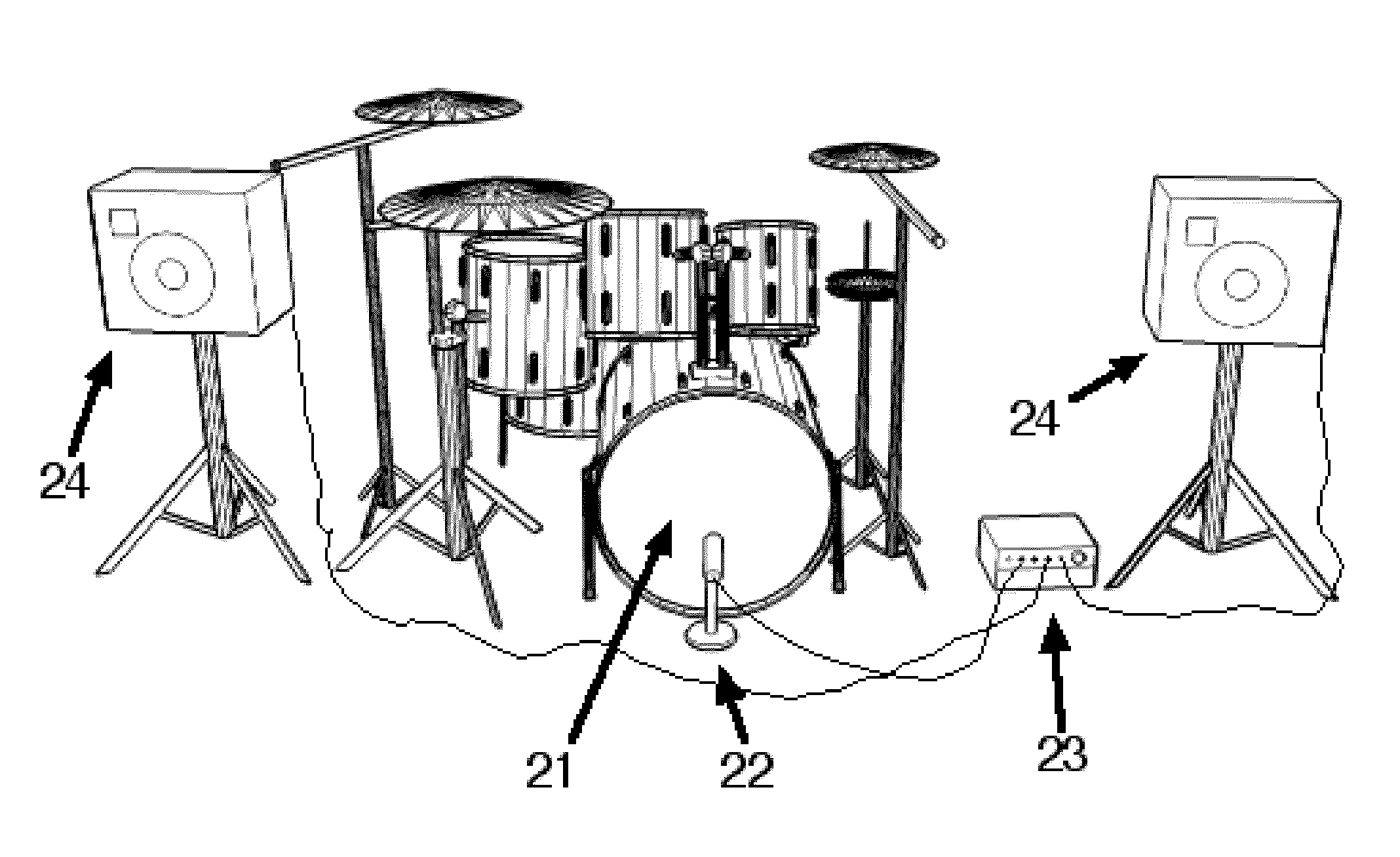
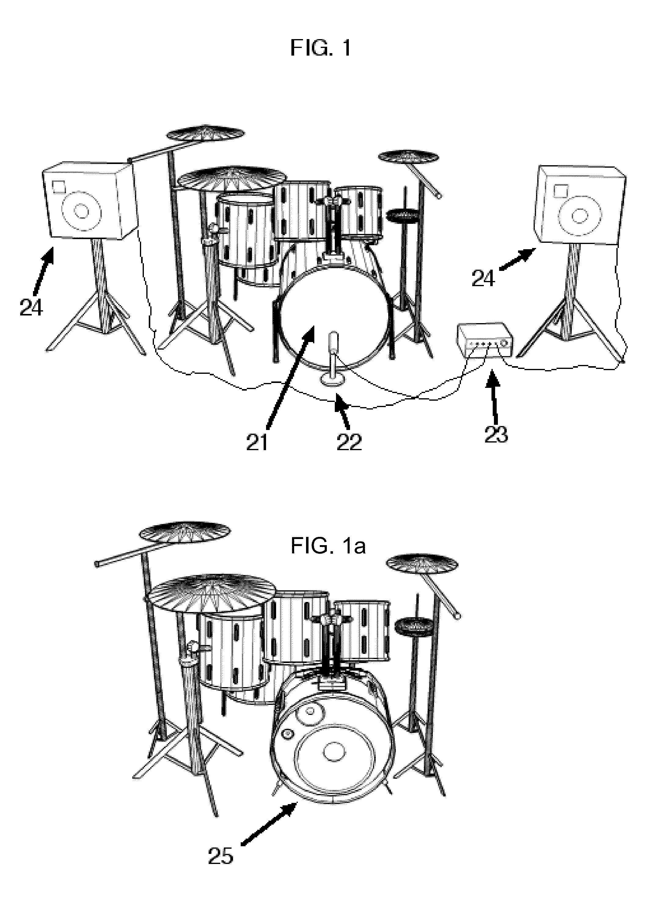
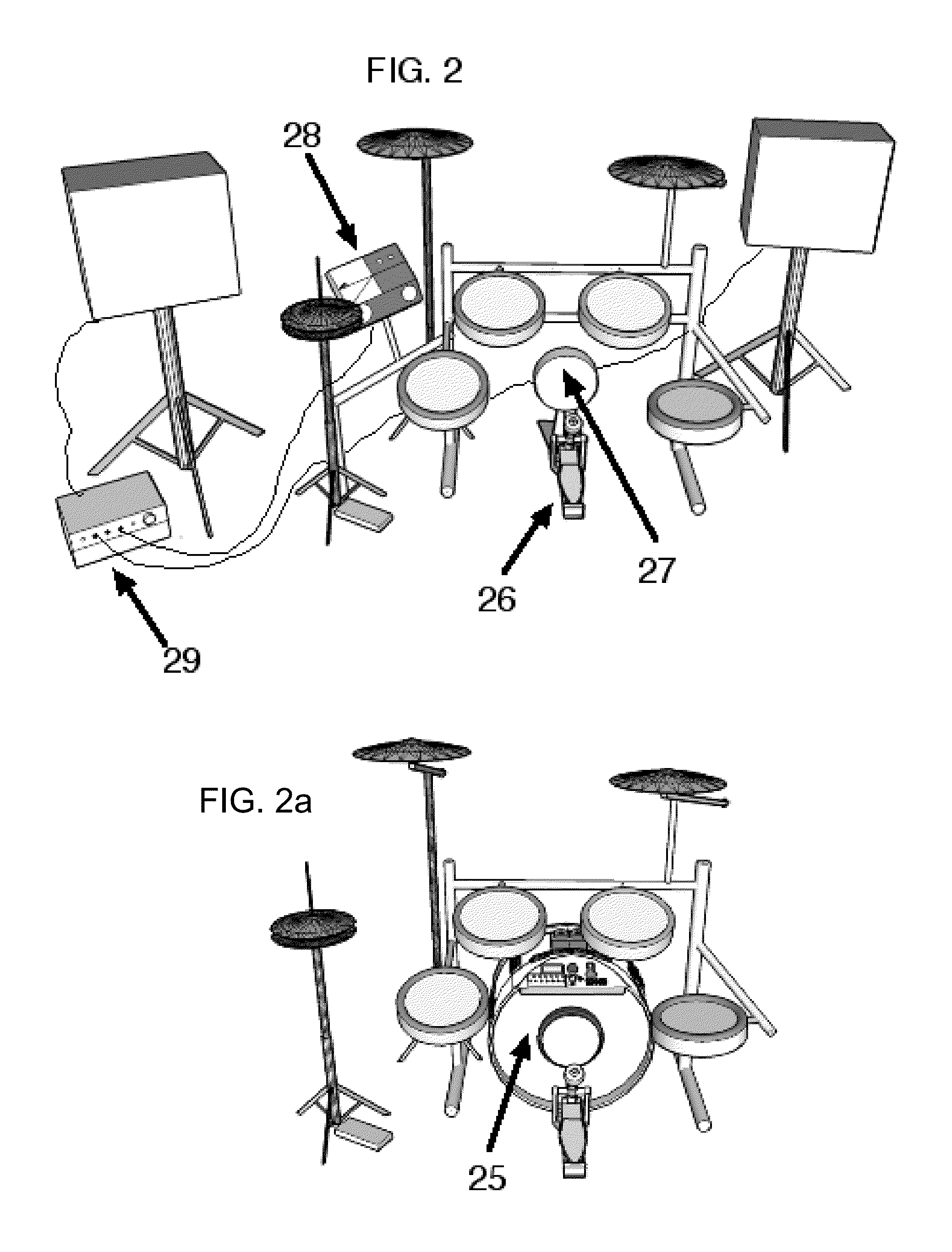
CROSS REFERENCE TO RELATED APPLICATION AND CLAIM TO PRIORITY[0001]This application claims the benefit of U.S. Provisional Application No. 6157593, filed Jul. 8, 2013.REFERENCES CITED[0002]U.S. Patent Documents:3,553,339January, 1971Dominguez et al6,956,596March, 2003Kuratani et al3,638,753August, 1970Cunningham6,982,376January, 2006Wise7,179,985February, 2007Pickens4,732,070March, 1988YamashitaSTATEMENT OF FEDERALLY SPONSORED RESEARCH / DEVELOPMENT[0003]NoneREFERENCE TO SEQUENCE LISTING[0004]NoneBACKGROUND OF THE INVENTION[0005]This invention relates generally to the field of musical instruments and more specifically to a complete system for an electronic bass drum.[0006]Virtually every drum kit has a bass drum, whether it is an acoustic set or an electronic set. This invention is designed to replace current bass drums in every type of drum set.[0007]In FIG. 1, a current technology acoustic drum set is presented, including a conventional acoustic bass drum. Note that there is the bass...

Claims


Application Information

Patent Timeline
Patent Type & Authority Applications(United States)
IPC IPC(8): G10H3/14G10D13/02
CPCG10D13/024G10H3/146G10D13/02G10D13/26G10H1/32G10H2230/291G10H1/348G10H3/18
Inventor STEELE, MARK D.
Owner STEELE MARK DAVID
Why Eureka
Try Eureka