Shielding arrangement for high-current applications

a shielding arrangement and high-current technology, applied in the direction of coupling protective earth/shielding arrangement, coupling device connection, aperture leaage reduction, etc., can solve problems such as requiring particular features to be compromised, and achieve effective fastening and contact, enlargement of effective contact surface, and advantageous distribution of press-on forces

Active Publication Date: 2016-07-28
ROBERT BOSCH GMBH
View PDF3 Cites 3 Cited by
  • Summary
  • Abstract
  • Description
  • Claims
  • Application Information

AI Technical Summary

Benefits of technology

The present invention is a connection system for high-current applications that improves mechanical stability, electrical contacting, and electromagnetic shielding. The system uses a wave-shaped design that prevents damage during fastening and increases the pull-off force required to destroy the shielding.

Problems solved by technology

In many cases, taking all these demands into account can require compromises with regard to particular features.

Method used


Image

  • Shielding arrangement for high-current applications
  • Shielding arrangement for high-current applications
  • Shielding arrangement for high-current applications

Examples


Embodiment Construction

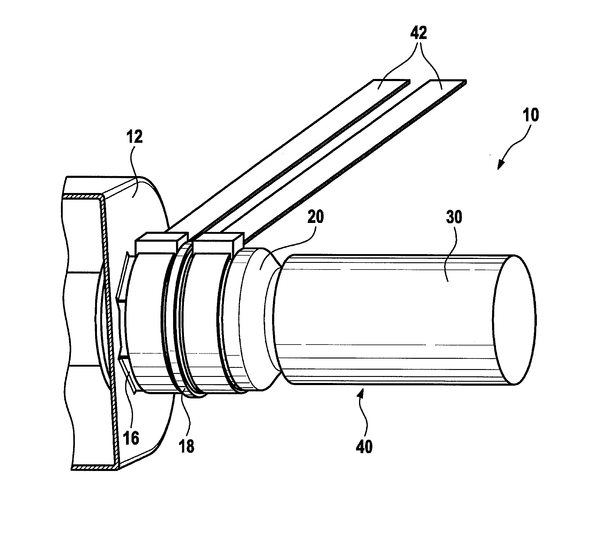
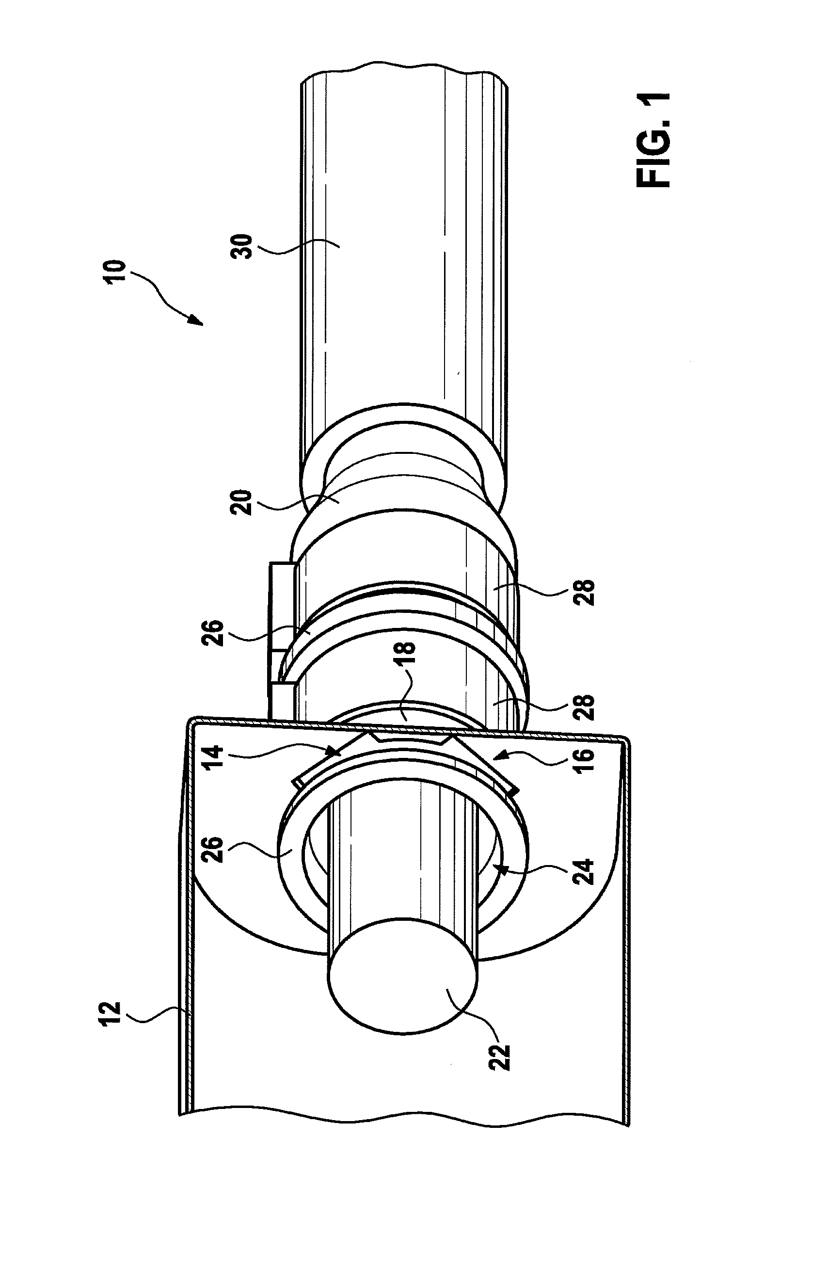
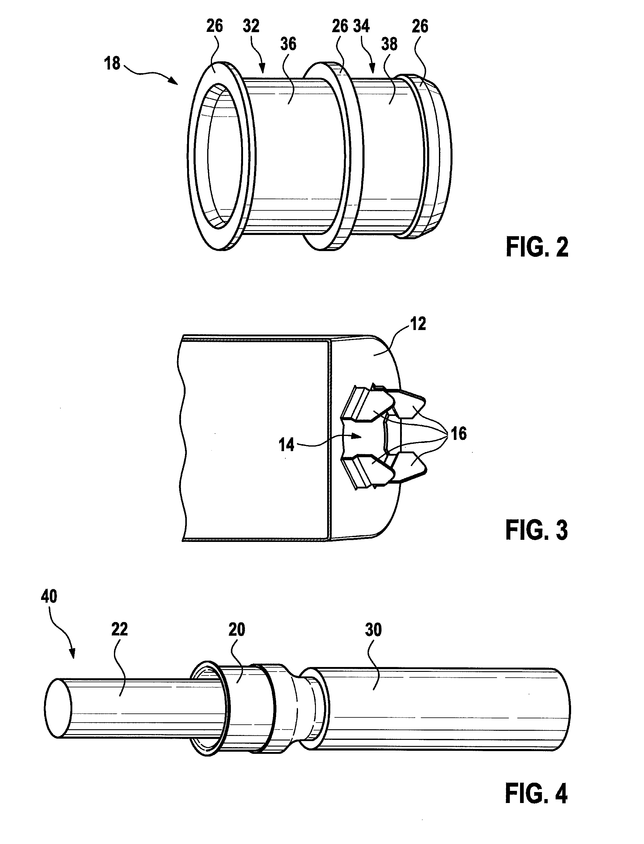
[0047]In FIG. 1, a shielding system 10 is shown for high-current applications, schematically and in a spatial representation. Shielding system 10 has a shielding housing 12 on whose side surface there is situated a feed-through 14. Extending out from feed-through 14, shielding housing 12 has a plurality of contact clips 16 that protrude orthogonally from the side surface of shielding housing 12. In feed-through 14 there is situated a shielding sleeve 18 that, in the example shown here, extends from shielding housing 12 up to a cable shielding 20. Cable shielding 20 is additionally surrounded externally at its circumference by an external insulating layer 30. Cable shielding 20 surrounds an insulated conductor 22 that is guided via a length of shielding sleeve 18 through shielding sleeve 18 at least into an internal region of shielding housing 12. In its internal region, insulated conductor 22 has an electrical conductor (not shown) that is surrounded by an insulation. For example, t...


PUM


Abstract

A shielding system for high-current applications, having a connecting cable that has an insulated conductor (22) and a cable shielding surrounding the insulated conductor, as well as a shielding housing having a feed-through. In addition, the shielding system has a hollow cylindrical and electrically conductive shielding sleeve. The insulated conductor is fed through the shielding sleeve. The shielding sleeve is situated in the area of the feed-through of the shielding housing, so that the shielding housing abuts a jacket surface of the shielding sleeve. The cable shielding lies against a jacket surface of the shielding sleeve. The cable shielding is electrically connected to the shielding housing via the shielding sleeve.

Description

FIELD[0001]The present invention relates to electrical connection systems. In particular, the present invention relates to a shielding system for connection systems in high-current applications.BACKGROUND INFORMATION[0002]Electrical connection systems can be used to produce an electrical connection between two or more components. This can be done by plug connections or lines.[0003]In particular, in the case of high-current applications, electromagnetic fields can arise around an electrical conductor. In order to avoid impairment of the environment around the conductor due to these electromagnetic fields, for example a surrounding shielding may be required. In the case of high-current lines, for example a shielding braid can be integrated in the line insulation for this purpose.[0004]Electromagnetic shieldings can also be required for connection systems. Due to the mechanical and electrical demands on these connection systems, and the occurrence of, in part, very high currents in the...

Claims


Application Information

Patent Timeline
Patent Type & Authority Applications(United States)
IPC IPC(8): H01R13/648H01R24/38
CPCH01R24/38H01R13/648H02G15/068H01R9/0524H05K9/0018H01R2103/00H01R13/53H01R13/6596H02G3/0616H02G3/083H05K9/0098
Inventor HU, ZHENYUSAUR, MARTIN
Owner ROBERT BOSCH GMBH
Why Eureka
Try Eureka