Component mounting machine

Active Publication Date: 2016-07-28
FUJI MASCH MFG CO LTD
View PDF8 Cites 10 Cited by
  • Summary
  • Abstract
  • Description
  • Claims
  • Application Information

AI Technical Summary

Benefits of technology

[0004]In order to solve such a problem, in recent years, the mounting head which is configured of a drive unit and a rotary head that is attachable to and detachable from the drive unit, and which can commonly use the drive unit with respect to plural types of rotary heads to be r

Problems solved by technology

However, in such a type of component mounting machine in the related art, since the entire mounting head including an R-axis drive device which rotates a rotary head or a θ-axis drive de

Method used


Image

  • Component mounting machine
  • Component mounting machine
  • Component mounting machine

Examples


Embodiment Construction

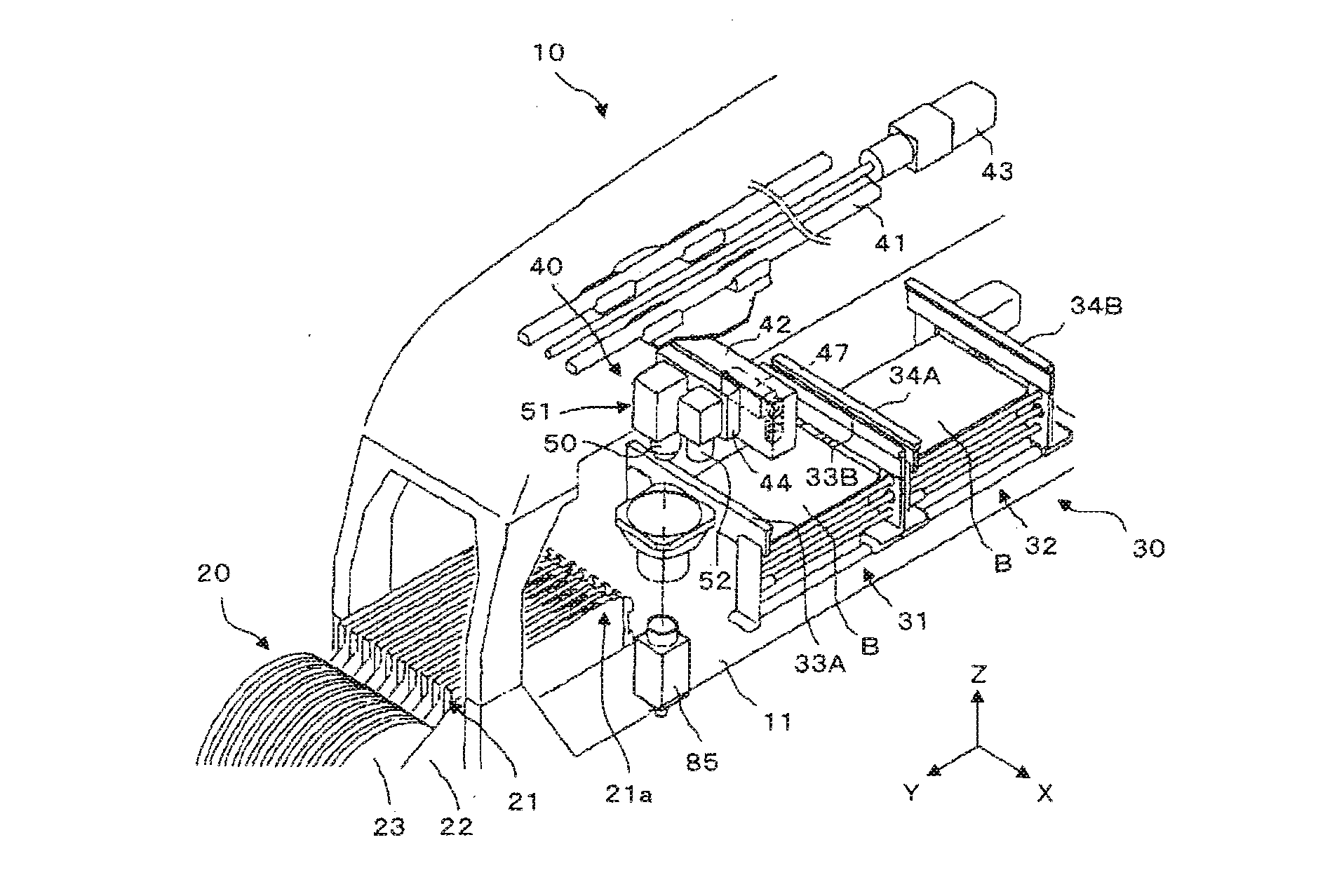
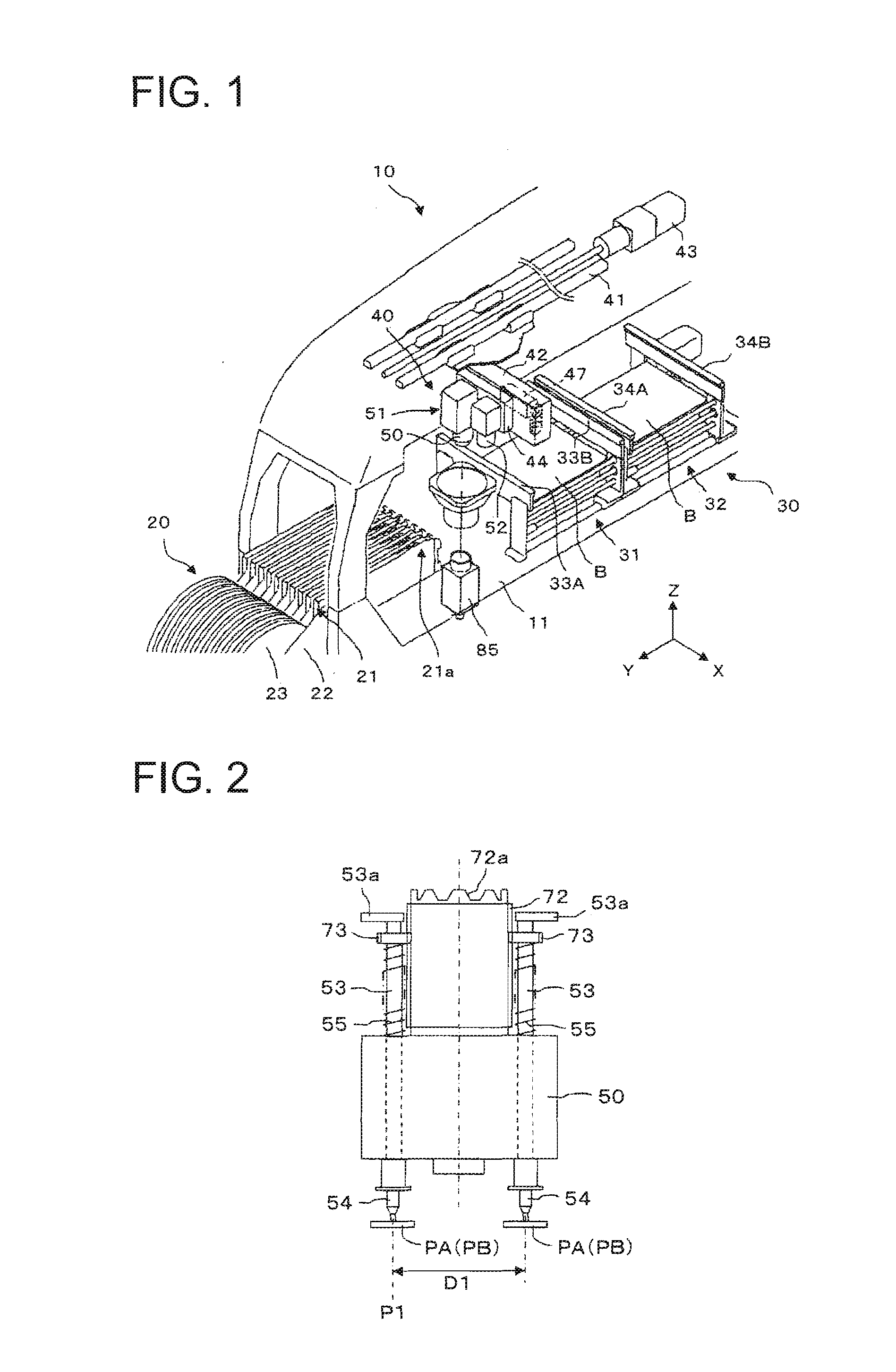
[0029]Hereinafter, the embodiment of the present invention will be described based on the drawings. As illustrated in FIG. 1, a component mounting machine 10 includes a component supply device 20, a board conveyance device 30, and a component transfer device 40.

[0030]As an example, the component supply device 20 is configured to align a plurality of tape feeders 21 in parallel to each other on a base 11 in an X-axis direction. The tape feeders 21 are detachably mounted to a main body frame 22 which is attached to be separable from the base 11, and include a supply reel 23 which winds tapes that accommodate multiple electronic components (hereinafter, referred to as components) in one row at an interval. Although not illustrated, inside the tape feeder 21, a motor which is driving source that pitch-feeds the tapes is embedded, the tape is sent out by one pitch by the motor, and the components accommodated in the tape are sequentially supplied to a component supply position 21a provid...


PUM


Abstract

A rotary head is configured of at least two types of rotary heads, such as a first rotary head in which four suction nozzles are respectively held to be rotatable on the circumference, and a second rotary head in which the suction nozzles of which the number is more than four are respectively held to be rotatable on a pitch circle diameter which is the same as that of the suction nozzle of the first rotary head, the first rotary head is attached to the drive unit, and a control device which controls an angular position of the first rotary head and an angular position of the components suctioned to the suction nozzles, to be respectively controlled to be changed by 45 degrees when the components held by the suction nozzles are imaged by a component camera is provided.

Description

TECHNICAL FIELD[0001]The present invention relates to a component mounting machine provided with a rotary head which holds a plurality of suction nozzles on a circumference.BACKGROUND ART[0002]As a suction nozzle which is held by a mounting head of a component mounting machine, a suction nozzle which appropriately corresponds to the type (size or shape) of the suctioned component is used. For this reason, an example in which the mounting head can be replaced corresponding to the type of the suctioned component is described in PTL1. However, in such a type of component mounting machine in the related art, since the entire mounting head including an R-axis drive device which rotates a rotary head or a θ-axis drive device which rotates the suction nozzle is configured to be replaced, the size and the weight of the head part to be replaced increase, and costs of the component mounting machine increase.CITATION LISTPatent Literature[0003]PTL 1: JP-A-2009-177213SUMMARY OF INVENTIONTechnic...

Claims


Application Information

Patent Timeline
IPC IPC(8): H05K13/04H05K13/08
CPCH05K13/08H05K13/0404H05K13/041H05K13/0812
Inventor NISHIYAMA, SATORU
Owner FUJI MASCH MFG CO LTD
Why Eureka
Try Eureka