Sealing structure of wheel bearing for vehicle and wheel bearing provided with the same

a technology for sealing structure and wheel bearings, which is applied in the direction of hubs, mechanical equipment, transportation and packaging, etc., can solve the problems of insufficient sealing purpose, insufficient sealing performance, and inability to effectively prevent the inflow of foreign materials, so as to achieve sufficient sealing purpose and improve sealing performance.

Active Publication Date: 2016-08-04
ILJIN GLOBAL
View PDF9 Cites 26 Cited by
  • Summary
  • Abstract
  • Description
  • Claims
  • Application Information

AI Technical Summary

Benefits of technology

[0013]The present invention has been made in an effort to provide a sealing structure of a wheel bearing having advantages of blocking foreign materials falling down on a surface of a flange and easily dropping the foreign materials down to a ground by forming a staying recess at a radially outmost end of the outer supporter.
[0014]Another embodiment of the present invention provides a sealing structure of a wheel bearing having advantages of tapping the foreign materials by forming a pocket lip at an inside of the sealing apparatus and of sending the trapped foreign materials out from the sealing apparatus.
[0015]Yet another embodiment of the present invention provides a sealing structure of a wheel bearing having advantages of preventing inflow of foreign materials in an axial direction by mounting a blocking wall extending to a radial outer direction from an exterior circumference of an inner supporter.
[0032]As described above, since a staying recess is formed between a radially outmost end of an outer supporter and a flange and a blocking wall is mounted on an exterior circumference of an inner supporter, inflow of foreign materials may be effectively prevented according to an exemplary embodiment of the present invention. If the foreign materials flow into a sealing apparatus, the foreign materials are trapped in a pocket lip and flow out from the sealing apparatus again. Further, the sealing apparatus according to an exemplary embodiment of the present invention may improve sealing performance, and thereby achieving sufficient sealing purpose even though one seal lip contacts with the outer supporter. Therefore, drag torque of the bearing may be reduced and fuel economy may be improved.

Problems solved by technology

Since such the wheel bearing is mounted at the wheel of the vehicle, the wheel bearing is always exposed to foreign materials such as dust and moisture.
If the foreign materials enter an inside of the wheel bearing, particularly a portion on which the rolling elements are mounted, raceways that are grinded may be damaged.
The damaged raceways may generate noise and vibration when the wheel bearing operates and may shorten a lifetime of the wheel bearing.
Furthermore, the inflow foreign materials cannot flow out from the conventional sealing apparatus.

Method used


Image

  • Sealing structure of wheel bearing for vehicle and wheel bearing provided with the same
  • Sealing structure of wheel bearing for vehicle and wheel bearing provided with the same
  • Sealing structure of wheel bearing for vehicle and wheel bearing provided with the same

Examples


Embodiment Construction

[0039]Exemplary embodiments of the present invention will hereinafter be described in detail with reference to the accompanying drawings.

[0040]In the specification, unless explicitly described to the contrary, the word “comprise” and variations such as “comprises” or “comprising”, will be understood to imply the inclusion of stated elements but not the exclusion of any other elements.

[0041]For better comprehension and ease of description, a portion close to a wheel in an axial direction (the left in the drawings) will be called ‘one side’, ‘one end’, ‘one end portion’ or similar designations thereto, and a portion far from the wheel in the axial direction (the right in the drawings) will be called ‘the other side’, ‘the other end’, ‘the other end portion’ or similar designations thereto.

[0042]In the specification, the same or similar reference numerals refer to the same or similar constituent elements.

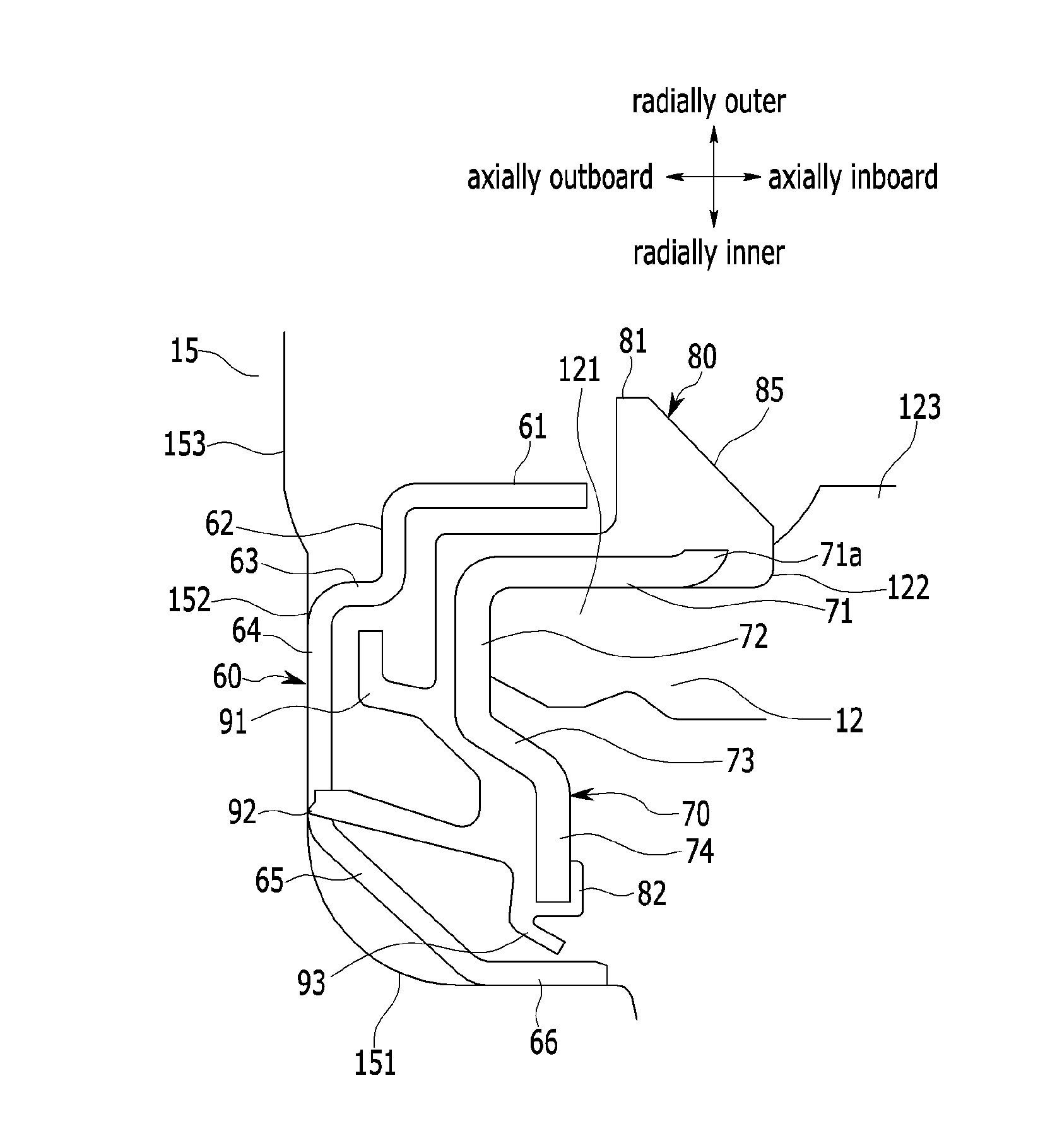
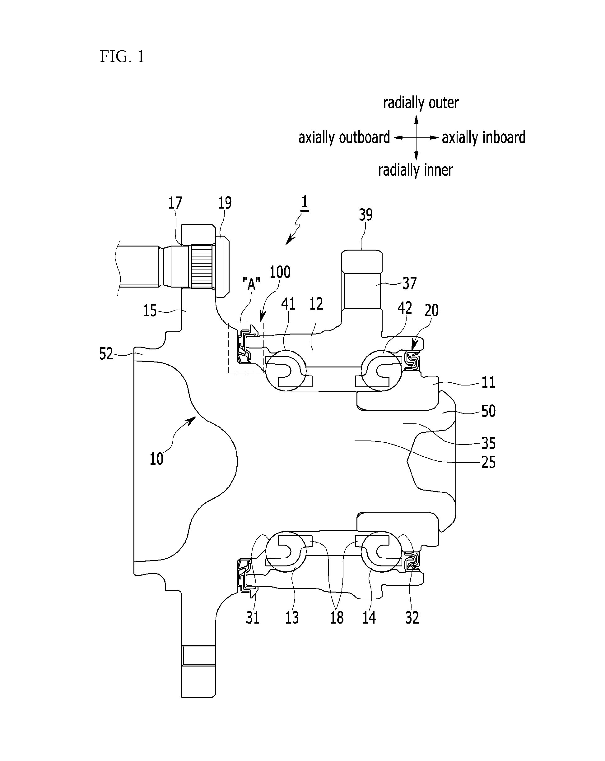
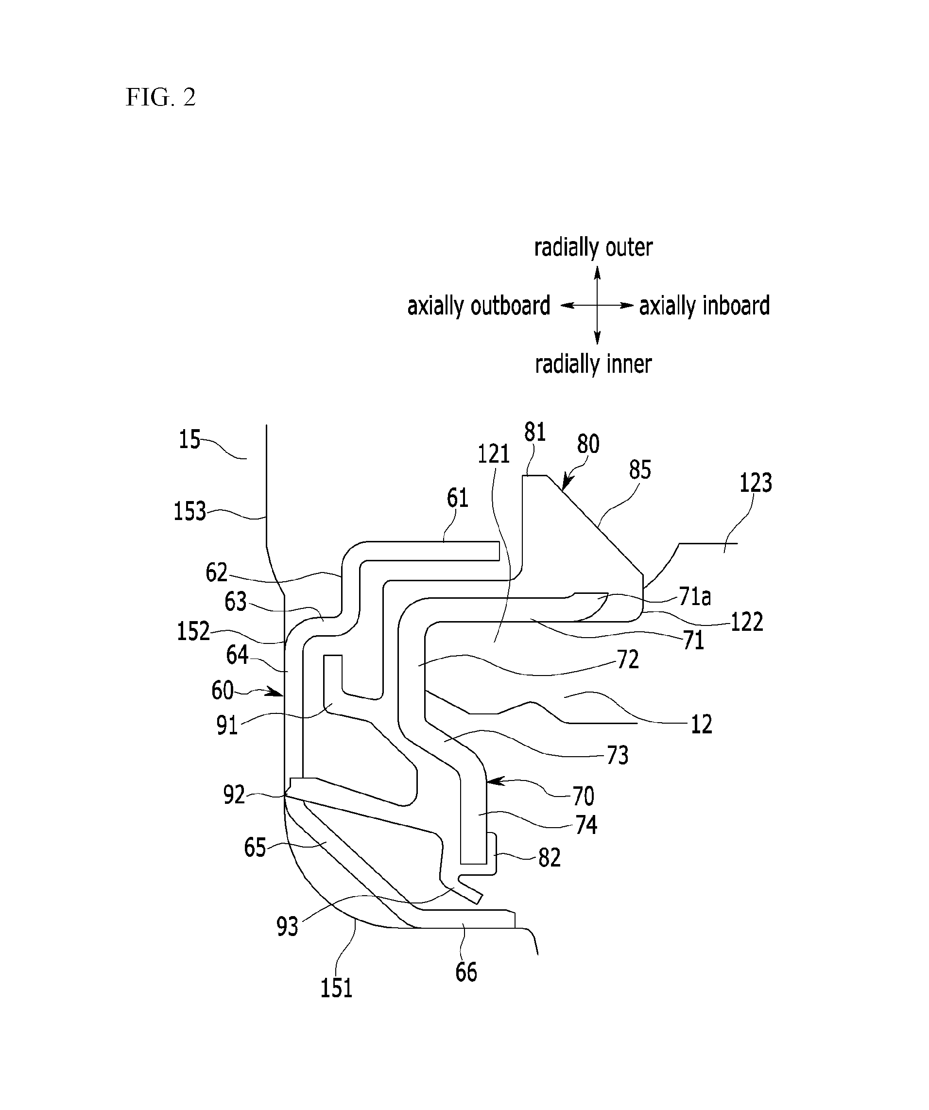
[0043]FIG. 1 is a cross-sectional view of a wheel bearing according to an exemplar...


PUM


Abstract

A wheel bearing includes a hub provided with a flange; and an outer ring having an end close to the flange and the other end opposite to the end and relatively rotatable to the hub. A sealing structure for sealing the space between the flange and the end of the outer ring is further included.

Description

CROSS-REFERENCE TO RELATED APPLICATION[0001]This application claims priority to and the benefit of Korean Patent Application No. 10-2015-0015451 filed in the Korean Intellectual Property Office on Jan. 30, 2015, the entire contents of which are incorporated herein by reference.BACKGROUND OF THE INVENTION[0002](a) Field of the Invention[0003]The present invention relates to a sealing structure of a wheel bearing for a vehicle. More particularly, the present invention relates to a sealing structure of a wheel bearing for a vehicle which is mounted between an outer ring and a flange of the wheel bearing for the vehicle and can prevent inflow of foreign materials, and the wheel bearing provided with the same.[0004](b) Description of the Related Art[0005]Generally, a bearing is disposed between a rotating element and a non-rotating element so as to smooth rotation of the rotating element. Various types of bearings such as a ball bearing, a taper roller bearing, needle bearing, and so on ...

Claims


Application Information

Patent Timeline
Patent Type & Authority Applications(United States)
IPC IPC(8): B60B27/00F16J15/00F16J15/3232F16J15/3268F16J15/447
CPCB60B27/0073F16J15/3268F16J15/447B60B2900/511F16J15/3232F16J15/002B60B27/001F16J15/3264F16J15/3456F16C33/7886F16C33/805F16C2326/02F16C19/186B60B35/18F16C33/76
Inventor LIM, JONG KEUNCHA, CHAE YOUNG
Owner ILJIN GLOBAL
Why Eureka
Try Eureka